
Flat gasket for a reciprocating engine or a driven machine

a technology of reciprocating engines and gaskets, which is applied in the direction of engine seals, machines/engines, sealing arrangements, etc., can solve the problems of limiting the service life of gaskets, gaskets exposed to dynamic loads, and stationary conditions over time cannot be achieved in sealing gaps, etc., to achieve improved sealing effect, low manufacturing cost, and high elastic resiliency

Inactive Publication Date: 2004-05-18
CARL FREUDENBERG KG
View PDF33 Cites 7 Cited by
  • Summary
  • Abstract
  • Description
  • Claims
  • Application Information

AI Technical Summary

Benefits of technology

The present invention provides a flat gasket with improved sealing effect, high elastic resiliency, low manufacturing costs, and long operating life. The flat gasket has at least two laminated metal sheets with a bead that surrounds the orifice of a combustion chamber or a liquid passage. The two metal sheets are permanently joined together on both sides of the bead, which causes the distance between the legs supporting the bead to be maintained even with changes in the sealing gap. This design increases the elastic resiliency of the bead and ensures a good sealing effect even with relative movements of the cylinder head and engine block. The flat gasket can be used as an enclosure for the combustion chamber and can also improve the sealing of the liquid seal. The bead has a high elastic resiliency, can maintain its shape even with movements, and can be designed to have different properties for the cylinder head and engine block. The flat gasket is cost-effective, easy to manufacture, and can have a long operating life.

Problems solved by technology

In addition to this static compressive load, the gasket is exposed to dynamic loads in operation of the engine.
A stationary condition over time cannot be achieved in the sealing gap either with the combustion chamber seal or the liquid seal.
The functional lifetime of this elastic resiliency essentially limits the service life of the gasket.
At the end of the service life, leaking occurs in the seal of the combustion chambers or the chamber passage orifices.

Method used


Image

  • Flat gasket for a reciprocating engine or a driven machine
  • Flat gasket for a reciprocating engine or a driven machine
  • Flat gasket for a reciprocating engine or a driven machine

Examples


Embodiment Construction

The object of the present invention is to provide a flat gasket having an improved sealing effect, a high elastic resiliency, low manufacturing costs and a long operating life.

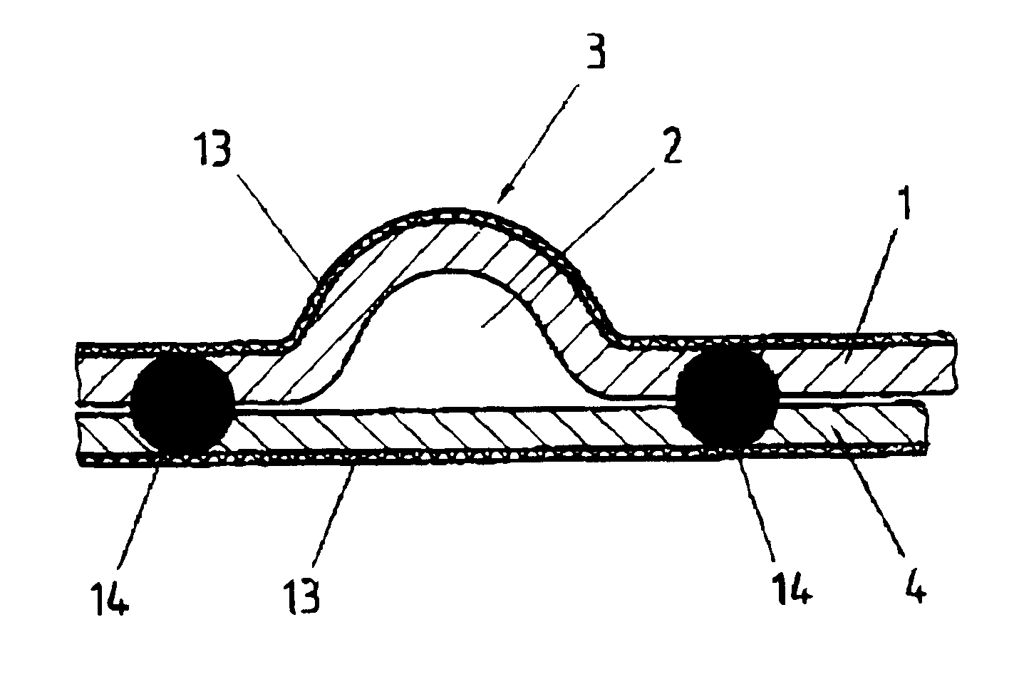
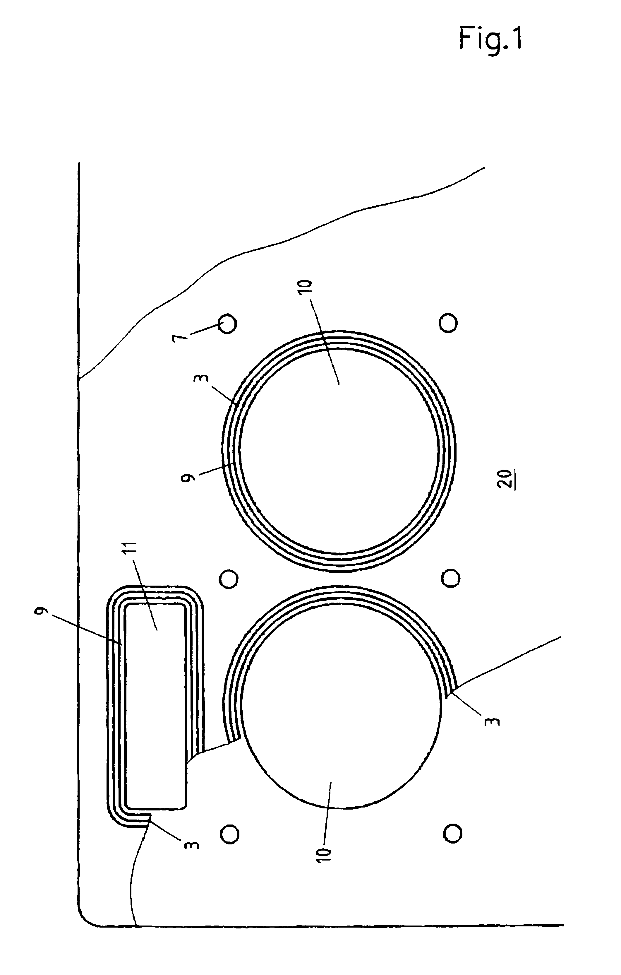
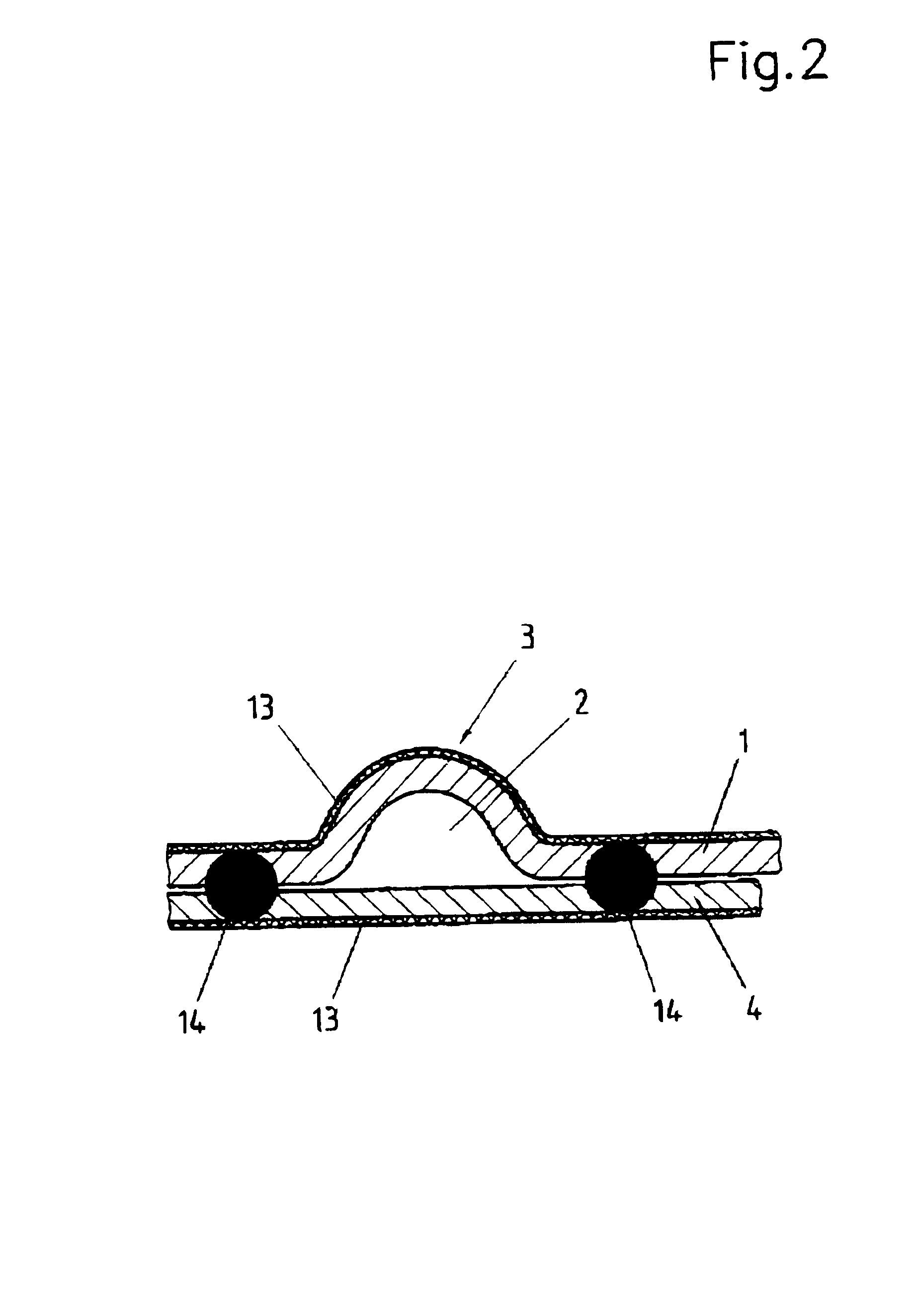
With the flat gasket according to the present invention, at least two laminated metal sheets are provided. One of these metal sheets has a bead which surrounds the orifice of a combustion chamber or a liquid passage. The other of these metal sheets bridges this bead, with the two metal sheets being permanently joined together on both sides of the bead. Due to this connection between the metal sheets, the flat gasket retains a very good elastic resiliency over a long period of operation. The sheet metal connection may completely enclose the orifice to be sealed or it may be designed in only spots or sections around the periphery, depending on the desired spring stiffness. The connection of the two metal sheets at the base of the bead causes the distance between the legs supporting the bead at the base of the be...


PUM


Abstract

A flat gasket for a reciprocating engine or a driven machine includes at least two laminated metal sheets 0.05 to 0.5 mm thick which are provided with a coating of an elastomer film at least on the side facing outward and have an edge area, formed by the outer contour and / or at least one cylinder bore and / or a water and / or oil passage in the cylinder head, adjacent to at least one peripheral first bead of one of the metal sheets, the second metal sheet bridging the first bead, both metal sheets being joined together permanently on both sides of the first bead.

Description

The present invention relates to a flat gasket for a reciprocating engine or a driven machine including at least two laminated metal sheets 0.05-0.5 mm thick which are provided with a coating of an elastomer film at least on the side facing outward and have an edge area, formed by the outer contour and / or at least one cylinder bore and / or a water or oil passage in the cylinder head, adjacent to at least one peripheral first bead of one of the metal sheets, the second metal sheet bridging the first bead.BACKGROUND INFORMATIONFlat gaskets for internal combustion engines or driven machines are known in a variety of embodiments, e.g., from German Patents 195 39 245, 195 31 232 and 42 05 824. In the case of engines for commercial vehicles, such cylinder head gaskets have the function of sealing the joint between the cylinder head and the cylinder block. They are usually made of one or more metal sheets joined together to form a laminate and have one or more combustion chamber passage ori...

Claims


Application Information

Patent Timeline
Patent Type & Authority Patents(United States)
IPC IPC(8): F16J15/08
CPCF16J15/0825F16J2015/085F16J2015/0856F16J2015/0875
Inventor HILGERT, CHRISTOPH
Owner CARL FREUDENBERG KG
Learn More