Conveying and/or storage device for packaged goods

a technology for conveying and/or storage devices, which is applied in the direction of transportation and packaging, conveying parts, storage devices, etc., can solve the problems of considerable impact pressure and inability to transport light-weight goods at all

Inactive Publication Date: 2004-04-13
DYNAMIC SYST ENG
View PDF39 Cites 17 Cited by
  • Summary
  • Abstract
  • Description
  • Claims
  • Application Information

AI Technical Summary

Benefits of technology

The device according to the invention is characterized in that the individual packaged goods, inasmuch as they are backed up on an obstacle, are subjected only to a minimal impact pressure. Also, in this case an increased loading of the drive of the roller path is avoided. Moreover, an especially smooth and uniform drive of the packaged goods transported on the roller path can be achieved. Even packaged goods, such as, for example, filled boxes of beverages of plastic material which are especially critical in the conventional storage and transport technology, can be processed trouble-free and with low wear on the transporting devices by means of the roller path according to the invention. The roller path can extend either horizontally, wherein the transport of the packaged goods is effected exclusively by the drive of the rollers or rolls, or the roller path can be slightly slanted. In the latter case, two transport mechanisms are used simultaneously. The first transport mechanism is the drive of the rollers or rolls of the roller path by means of a common drive means. The second drive mechanism is the effect of the force of gravity as result of the descending roller path. This double movement mechanism results in an excellent uniformness in the transport speed of the packaged goods independent of their weight and size. Even packaged goods with high specific weight such as, for example, beverage boxes are transported as quickly and with almost constant transport speed along the roller path such as particularly lightweight packages, for example, cardboard packages with potato chips or packages with toilet paper. In regard to a slanted arrangement of the roller path, a slant angle of the roller path of 2.5 to 6%, preferably 3 to 5.5%, has proven to be especially suitable for obtaining such a uniform transport.
According to a preferred configuration, the force transmitting element is a bushing supported rotatably on a bearing portion of the roller or roll. A targeted, even though only minimal, friction between the freely rotating bushing and the roller or roll is obtained. This causes a very "smooth" drive of the roll with only minimal drive or torque moments while upon increase of this drive moment the friction surfaces between bushing and roller or roll will slip so that no significant torque is transmitted from the bushing onto the roll. The coefficient of friction between roller or roll and the bushing is smaller than the transmittable torque between the common drive means and the bushing. The thus obtained "smooth" drive of the rolls results in a reduction of the conveying pressure of the roller path so that only minimal pressure is exerted primarily onto the piece of packaged goods arranged in the leading position at the removal end of the storage aisle. It is furthermore advantageous that also the removal devices, as a result of the reduced impact pressure of the goods, can be operated with reduced drive power.
For obtaining a uniform drive action, it is also moreover advantageous when the bushing is provided at its end facing the roller or roll with a circumferential collar. The drive belt can run up against this collar without laterally slipping off the drive surface of the bushing.
Each storage aisle can be provided with a removal device, and the components of the removal devices can be in the form of a retaining element projecting into the transport path of the roller path and a horizontal conveyor arranged in the conveying direction behind the retaining element whose transport speed is greater than the transport speed of the roller path. Preferably, the conveying speed of the horizontal conveyor is at least 25% greater than the transport speed of the roller path. In this way, a safe and trouble-free separation of the frontmost piece of packaged goods to be removed is achieved from the packaged goods positioned therebehind and transported on the roller path.

Problems solved by technology

Inasmuch as the roller paths are slanted, it is problematic to configure them uniformly optimized for all types of packaged goods.
When the slant angle of the roller paths is too small, this can result in the light-weight goods not to be transported at all.
In the case of several package goods arranged successively in the aisle, considerable impact pressure can result which is also caused only by the effect of the force of gravity.

Method used


Image

  • Conveying and/or storage device for packaged goods
  • Conveying and/or storage device for packaged goods
  • Conveying and/or storage device for packaged goods

Examples


Embodiment Construction

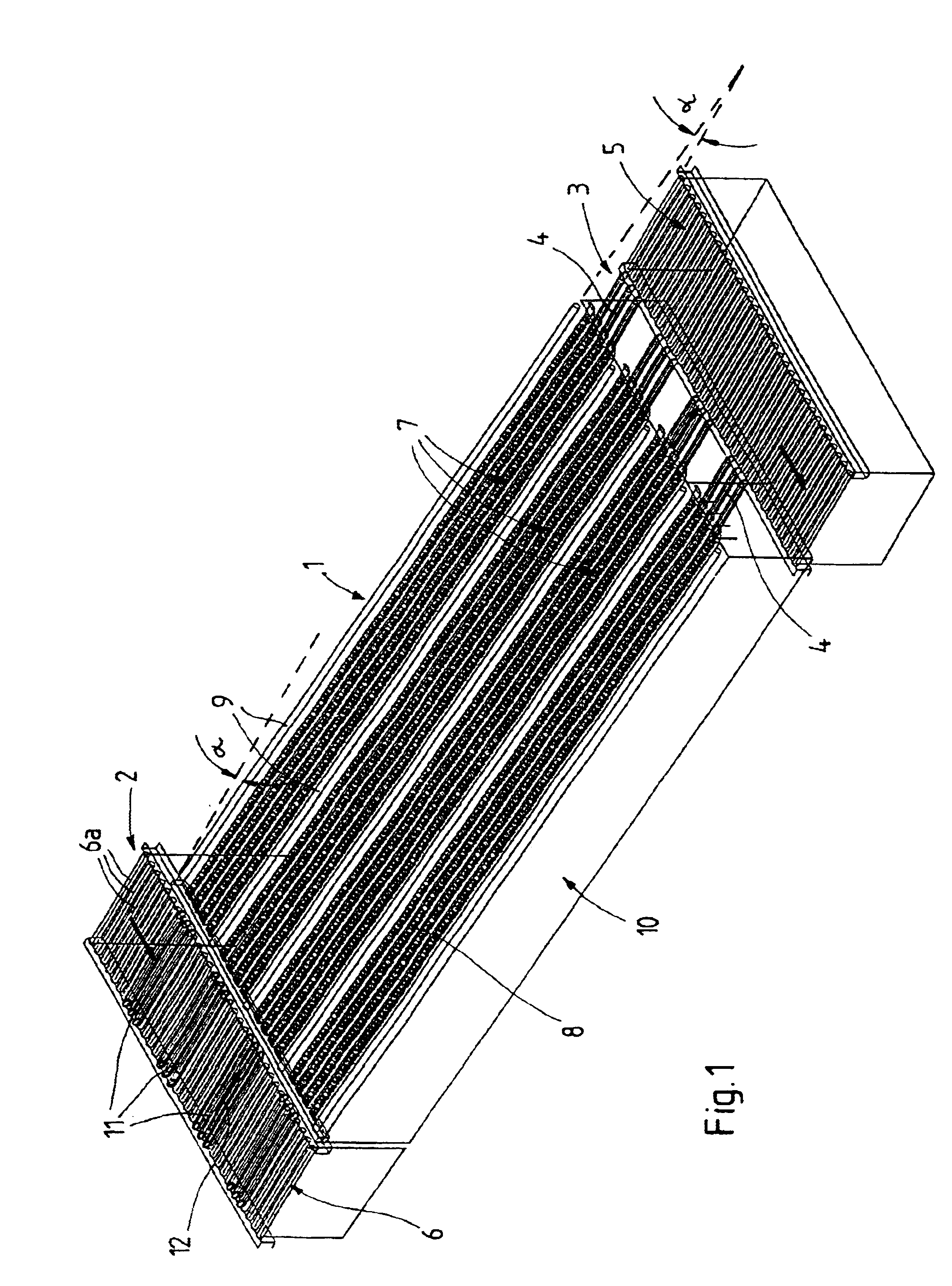
The commissioning storage device for packaged goods, including beverage boxes, and for groceries in cardboard boxes, which have a very high turnover rate in wholesale, is comprised primarily of a storage area 1, a supply area 2 arranged upstream of the storage area 1, and a commissioning area 3 downstream of the storage area 1. In the supply area 2 the packaged goods to be newly stored are distributed to the correct storage location within the storage area 1. In the commissioning area 3 the individual packaged goods are then removed according to the commission by computer control from the storage area 1 and transported to a location where the combination and optionally packaging of the commissions to larger packaged arrangements is realized. For removal of the individual goods from the storage area 1, removal devices 4 are provided which place the individual goods removed from the storage area 1 on a transport path 5 arranged downstream along which the further transport of the goods...


PUM


Abstract

A transport and storage device for packaged goods has at least one roller path for goods to be transported and stored, wherein the at least one roller path has rollers. Force transmitting elements are arranged rotatably on the rollers, wherein the force transmitting elements are bushings having an inner surface, respectively. A common drive is provided for rotating the rollers, wherein a first torque transmittable between the bushings and the corresponding rollers, respectively, is smaller than a second torque transmittable between the common drive and the bushings. The rollers have a bearing section fixedly connected with the rollers, respectively. The inner surfaces of the bushings are rotatably supported on the bearing section of the rollers.

Description

1. Field of the InventionThe invention relates to a transport and / or storage device for packaged goods, comprising at least one aisle formed as a roller path for the goods to be transported and / or stored.2. Brief Description of the Related ArtIn the storage and commission technology shelf constructions of several levels are known with adjacently positioned and stacked storage aisles for the packaged goods. The shelves of the storage aisles are provided with roller paths of rotating rollers for transporting the packaged goods and, generally, are slanted slightly toward the removal side so that the goods supplied at the one end of the storage aisles, the so-called loading or supply side, will move along the roller paths to the other end of the storage aisles where the receiving area is arranged. The supply of the packaged goods at the loading side can be performed manually in that the individual packaged goods are removed from a pallet and placed into the correlated storage aisle. Oft...

Claims


Application Information

Patent Timeline
IPC IPC(8): B65G13/07B65G13/02B65G1/06B65G47/53B65G47/54
CPCB65G1/06B65G13/07B65G47/54
Inventor HOLLANDER, RUDOLF
Owner DYNAMIC SYST ENG
Why Eureka
Try Eureka