
Shift lever unit

a technology of shift lever and unit, which is applied in the direction of gearing control, mechanical control devices, restricting/preventing/returning the movement of parts, etc., can solve the problems of high cost, inability to accept electrically controlled gearboxes, and necessary maintenance work for regular lubrication, etc., and achieve the effect of compact size of the shift lever uni

Inactive Publication Date: 2004-04-13
TRIAD FICO +2
View PDF22 Cites 33 Cited by
  • Summary
  • Abstract
  • Description
  • Claims
  • Application Information

AI Technical Summary

Benefits of technology

Preferably, the rotating element is arranged above a suspension of the shift lever, so that a compact size of the shift lever unit is obtained. This further allows an easy access to the sensor in case a repair or a replacement is necessary.

Problems solved by technology

This purely mechanical control, however, involves all disadvantages which arc related to the use of moving mechanical parts.
For example, considerable maintenance work is necessary for the regular lubrication of the bowden cables or the bearings of the linkage.
Further, the replacement of one of the mechanical components causes high costs, since at least parts of the shift lever unit and the gearbox as well as the bowden cables or the linkage have to be taken apart and subsequently put together again.
In spite of these advantages, electrically controlled gearboxes have up to now not been accepted.

Method used


Image

  • Shift lever unit
  • Shift lever unit
  • Shift lever unit

Examples


Embodiment Construction

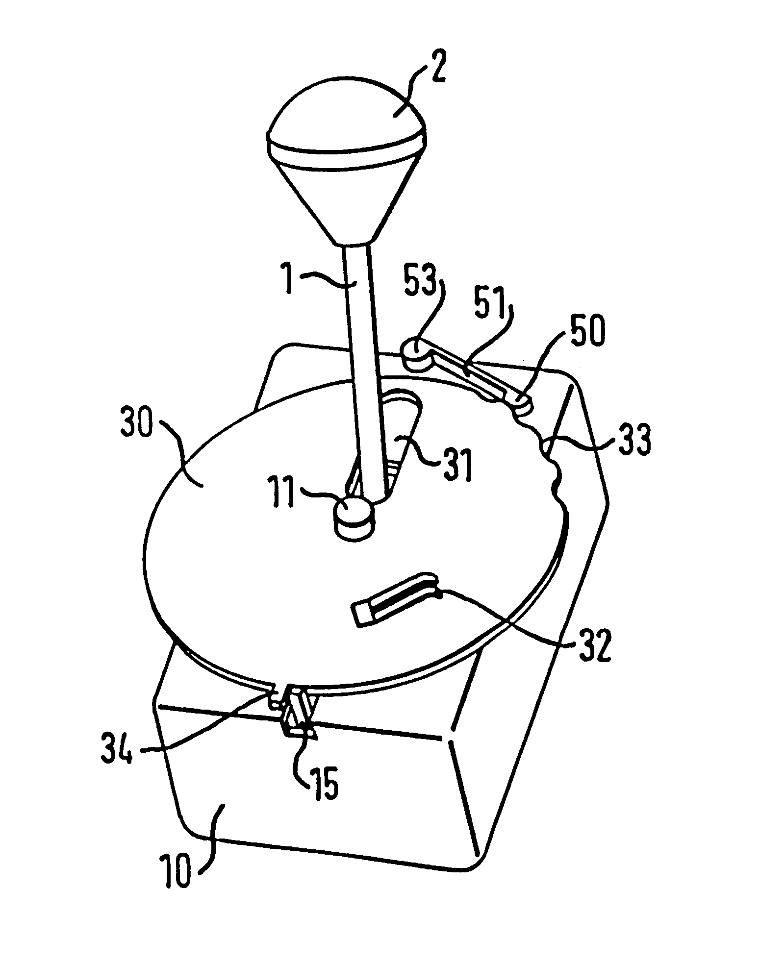
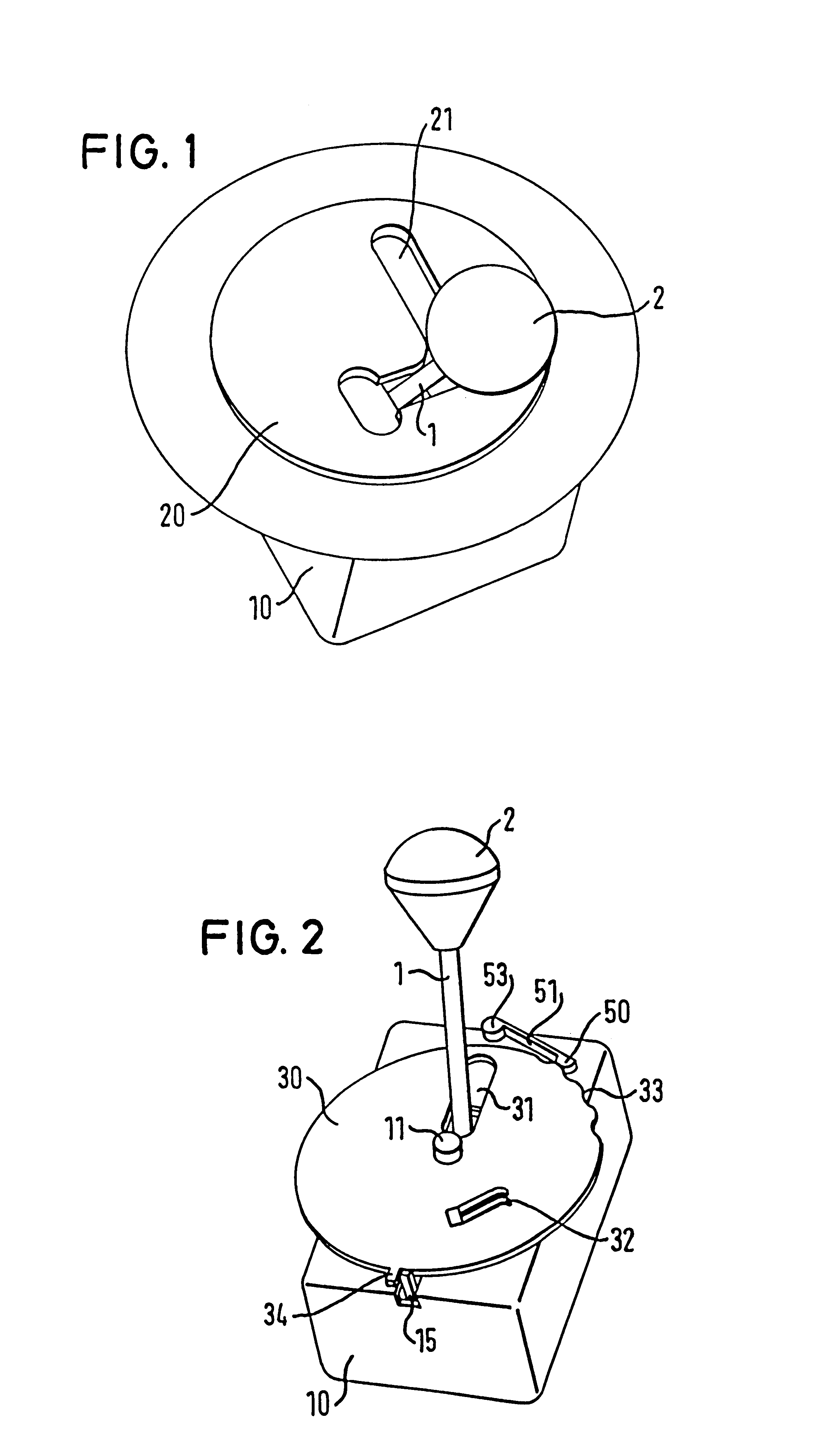
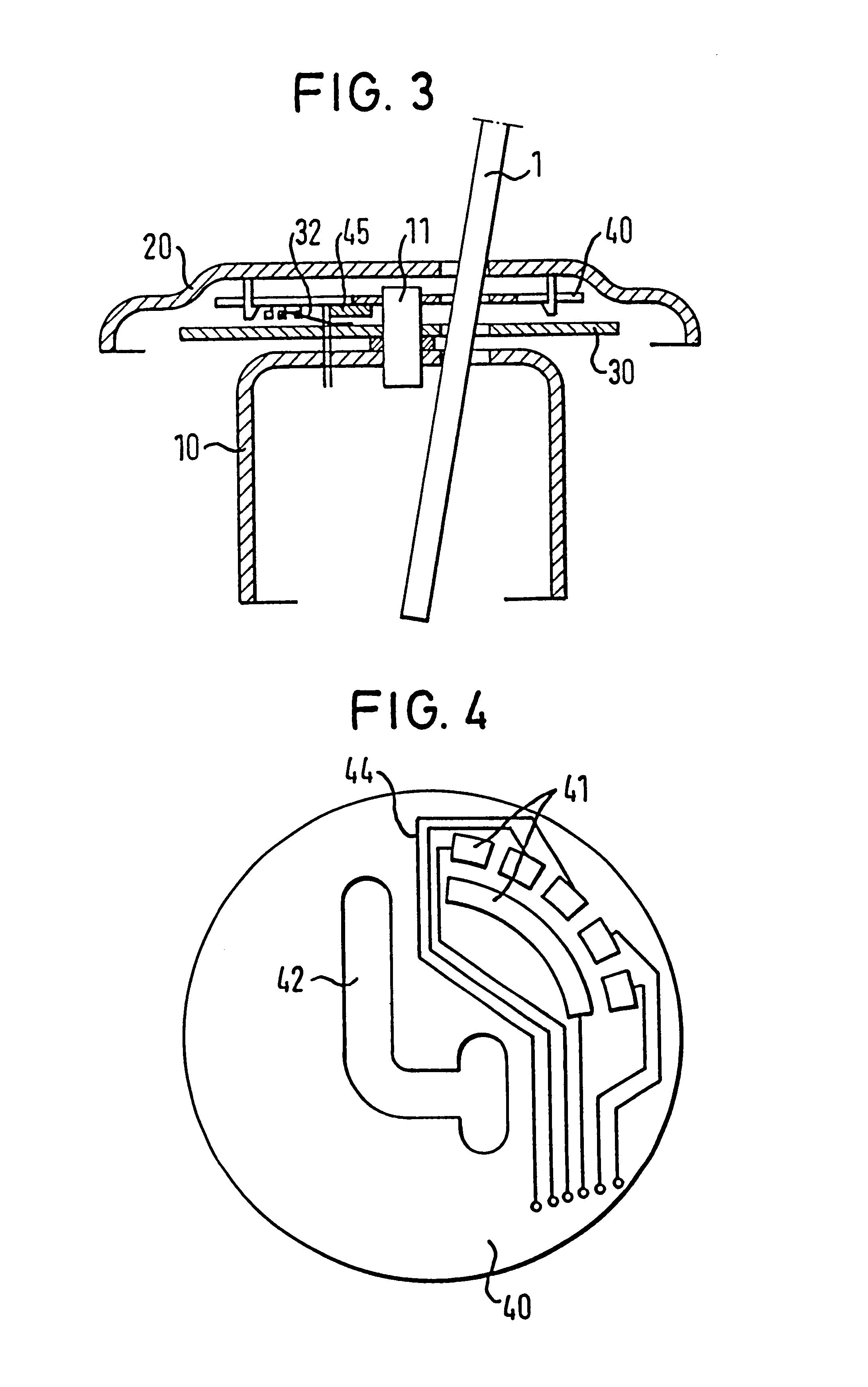
With reference to the embodiment shown in FIG. 1 the shift lever unit comprises a shift lever 1 having a bearing in a housing 10 so that it can be tilted in several directions. This may preferably be achieved by a suspension on several rotating axes (not shown) or by the use of a ball-and-socket joint (not shown). At its upper end, the shift lever 1 has a knob 2 for moving the shift lever 1.

The other components of the shift lever unit are preferably covered by the cover 20 having preferably in its center a sparing 21 in which the shift lever moves and whose shape corresponds to the gear shifting gate 16 (see below). The sparing 21 is simplified shown in FIG. 1 having the shape of a mirrored "L"; depending on the number of gears more complex shapes will be used in reality. The design of the cover, that is, its external shape, color etc. may be adapted to the design of the interior of the vehicle and is without any influence on the functions of the shift lever unit. Alternatively to t...


PUM


Abstract

Shift lever unit for transforming the tilting movements of a shift lever (1) in electrical control signals, in particular for controlling a gearbox, with a shift lever, a rotating element (30, 3') which is rotated by the tilting movements of the shift lever (1) and a sensor (32, 41) detecting the angular position of the rotating element (30, 3') and transforming it into electrical signals.

Description

1. TECHNICAL FIELDThe present invention relates to a shift lever unit for transforming the movements of a shift lever in electrical controls signals. The invention relates in particular to a shift lever unit for the electrical control of a gearbox, preferably for the use in a motor vehicle.2. THE PRIOR ARTIn a motor vehicle the movements of a shift lever for changing the gears are typically mechanically transmitted to the gearbox of the vehicle. To this end, the tilting of the shift lever is in the shift lever unit transformed in longitudinal movements of several bowden cables or a linkage. The bowden cables or the linkage are connected to the gearbox and cause the changing of the gears.This purely mechanical control, however, involves all disadvantages which arc related to the use of moving mechanical parts. For example, considerable maintenance work is necessary for the regular lubrication of the bowden cables or the bearings of the linkage. Further, the replacement of one of the ...

Claims


Application Information

Patent Timeline
IPC IPC(8): F16H59/04B60K20/02F16H61/00
CPCF16H59/044F16H61/24Y10T74/20098Y10T74/20159Y10T74/20128Y10T74/2003Y10T74/20085
Inventor BOFIAS, JOSEP
Owner TRIAD FICO
Learn More