
Gridless time-of-flight mass spectrometer for orthogonal ion injection

a time-of-flight and mass spectrometer technology, applied in the field of time-of-flight mass spectrometers, can solve the problems of no spectrometer which is better than a time-of-flight mass spectrometer, small-angle scatter at the openings in the grid cannot be reduced, and only small-angle scatter can be reduced

Inactive Publication Date: 2004-04-06
BRUKER DALTONIK GMBH & CO KG
View PDF23 Cites 63 Cited by
  • Summary
  • Abstract
  • Description
  • Claims
  • Application Information

AI Technical Summary

Benefits of technology

The solution effectively focuses ions on a small-area detector, reducing noise and enhancing mass resolution without the drawbacks of grid-based systems, allowing for high temporal and mass resolving power.

Problems solved by technology

For measurement of the mass of large molecules by mass spectrometry, as particularly occurs in biochemistry, there is no spectrometer which is better than a time-of-flight mass spectrometer because of the limited mass ranges of other mass spectrometers.
Divergence due to the spread of initial velocities can be reduced by selecting a high acceleration voltage but the small-angle scatter at the openings in the grid cannot be reduced.
This small-angle scatter can only be reduced by making nets of finer mesh, albeit at the expense of grid transparency.
This large-area detector has disadvantages: a high level of noise and the necessity of very good two-dimensional directional adjustment in order to keep the flight path differences well below one micrometer.
In addition there will be a non-negligible number of ions which are reflected by the grids and can be scattered back to the detector where they create background noise, which worsens signal-to-noise ratio.
The advantages of having only one grid (only two ion passages instead of four) and having to generate only one adjustable voltage are offset by considerable drawbacks: The mechanical design calls for many more diaphragms for homogenization of the reflection field; the long stay of the ions in the reflection field, however, leads to an increase in metastable decompositions in the reflector and therefore to diffused background noise in the spectrum because the decomposing ions turn back somewhere in the reflector due to changed energies so they cannot be temporally focused.
All the mass spectrometers known for orthogonal injection, however, have the very disadvantageous grids (due to the band-shaped ion beam which does not permit spherical lenses), both in the pulser and in the reflector.

Method used


Image

  • Gridless time-of-flight mass spectrometer for orthogonal ion injection
  • Gridless time-of-flight mass spectrometer for orthogonal ion injection
  • Gridless time-of-flight mass spectrometer for orthogonal ion injection

Examples


Embodiment Construction

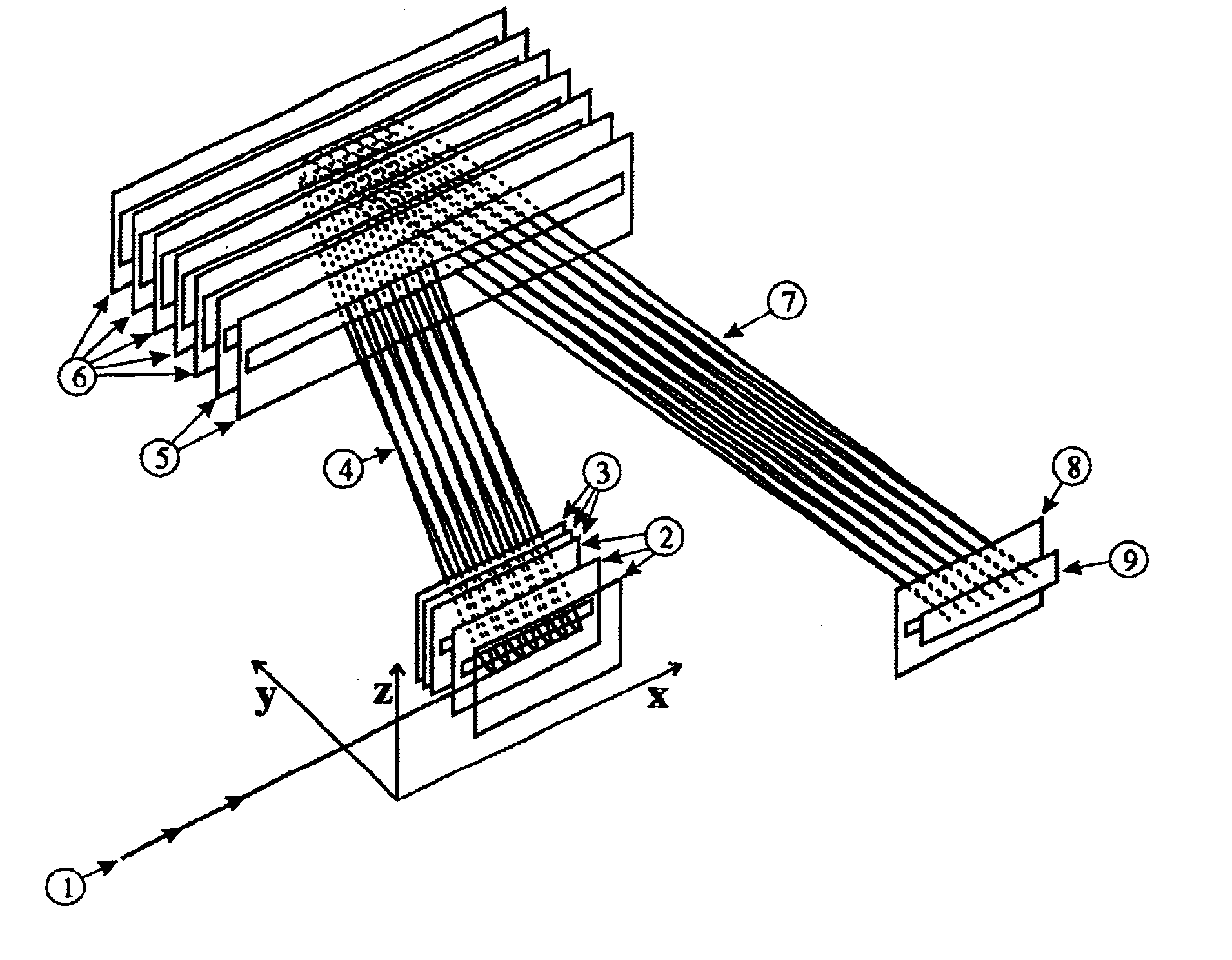
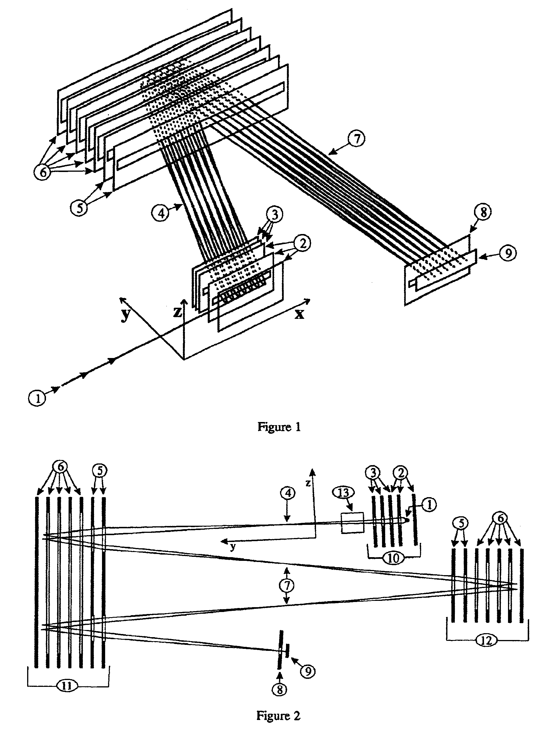
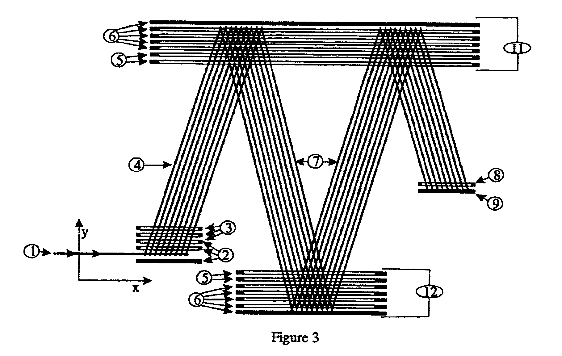
A preferred embodiment is depicted in FIG. 1. A fine primary ion beam (1), which defines the x-direction, is injected into the purser (2). The fine ion beam can originate from an electrospray ion source, for example. The pulser (2) consists of three electrodes, of which the first electrode acts as a repeller electrode and the second and third electrodes take the form of slit diaphragms. The ion beam consists of ions with low kinetic energy of approx. 4 to 40 electron-volts, which are injected into the space between the repeller electrode and the first slit diaphragm; the ions therefore fly relatively slowly, whereby the velocity depends on mass. (To be more accurate, the velocity depends on the ratio between the mass and the charge m / e, but for the sake of simplicity reference is only made to the mass m). While the pulser is being filled with ions the first two electrodes are at ambient potential so they do not disturb the flight of the ions. The third electrode is at acceleration p...


PUM


Abstract

The invention relates to a time-of-flight mass spectrometer for injection of the ions orthogonally to the time-resolving axis-of-flight component, with a pulser for acceleration of the ions of the beam in the axis-of-flight direction, preferably with a velocity-focusing reflector for reflecting the ion beam and with a flat detector at the end of the flight section. The invention consists of using, both for acceleration in the pulser and for reflection in the reflectors, a gridless optical system made up of slit diaphragms which can spatially focus the ions onto the detector in the direction vertical to the directions of injection and flight axis, but which does not have any focusing or deflecting effect on the other directions. For some reflector geometries it is essential to use an additional cylindrical lens for focusing, and for other reflector geometries the use of such a lens may be advantageous.

Description

The invention relates to a time-of-flight mass spectrometer for injection of the ions orthogonally to the time-resolving axis-of-flight component, with a pulser for acceleration of the ions of the beam in the axis-of-flight direction, preferredly with a velocity-focusing reflector for reflecting the ion beam and with a flat detector at the end of the flight section.The invention consists of using, both for acceleration in the pulser and for reflection in the reflectors, a gridless optical system made up of slit diaphragms which can spatially focus the ions onto the detector in the direction vertical to the directions of injection and flight axis, but which does not have any focusing or deflecting effect on the other directions. For some reflector geometries it is essential to use an additional cylindrical lens for focusing, and for other reflector geometries the use of such a lens may be advantageous.PRIOR ARTTime-of-flight mass spectrometers, which have been known for over 50 years...

Claims


Application Information

Patent Timeline
Patent Type & Authority Patents(United States)
IPC IPC(8): G21K1/00G21K1/06
CPCH01J49/06H01J49/401H01J49/405
Inventor FRANZEN, JOCHEN
Owner BRUKER DALTONIK GMBH & CO KG
Learn More