
Dual-slip compressive shrink-proofing apparatus for fabric and related method

a compressive and fabric technology, applied in the direction of shaping/stretching tubular fabrics, knitting, weaving, etc., can solve the problems of not being formed or requiring frequent re-adjusting of compression zones, and knitting textile fabrics, like randomly deposited fabrics, are neither formed nor structured similarly to woven textile fabrics, etc., to achieve superior-quality controlled permanent compaction

Inactive Publication Date: 2004-01-27
CATALLO FRANK
View PDF19 Cites 22 Cited by
  • Summary
  • Abstract
  • Description
  • Claims
  • Application Information

AI Technical Summary

Benefits of technology

It is therefore an object of the present invention to provide an apparatus and related method to produce superior-quality controlled permanent compaction of knitted textile and similar fabrics.
It is still further object of the present invention to reduce power requirements of the apparatus.

Problems solved by technology

Although these compactors produce generally acceptable shrink-proofing results, they are temperamental and require frequent re-adjusting of their compression zones.
However, knitted textile fabrics, like randomly deposited fabrics made of natural or man-made fibers, are neither formed nor structured similarly to woven textile fabrics.
Yet such an ideal image of stitch rows through a compactor rarely finds its counterpart in the real world.
Knitted textile fabrics frequently are not designed with straight transverse stitch rows.
As has been noted herein, technology which evolved from compacting of woven textile fabric webs generally has achieved inconsistent success in treating knitted textile fabrics.
Lack of consistent success has been common to compaction of knitted textile fabrics both as tubes and as open webs.
In actual knitted textile fabrics we frequently can expect unreliable orientation (skewing) of stitch rows formed of interlocked yarn loops.
Simultaneously, a series of companion transverse vectors of any or all of the same points could thereby be either wasted or they could contribute to counterproductive stretching.
Accordingly a substantial portion of longitudinal compacting effort on knitted textile fabrics was self-defeating when performed through the crimped, bent, kinked or otherwise obstructed compression zones of the prior art.

Method used


Image

  • Dual-slip compressive shrink-proofing apparatus for fabric and related method
  • Dual-slip compressive shrink-proofing apparatus for fabric and related method
  • Dual-slip compressive shrink-proofing apparatus for fabric and related method

Examples


Embodiment Construction

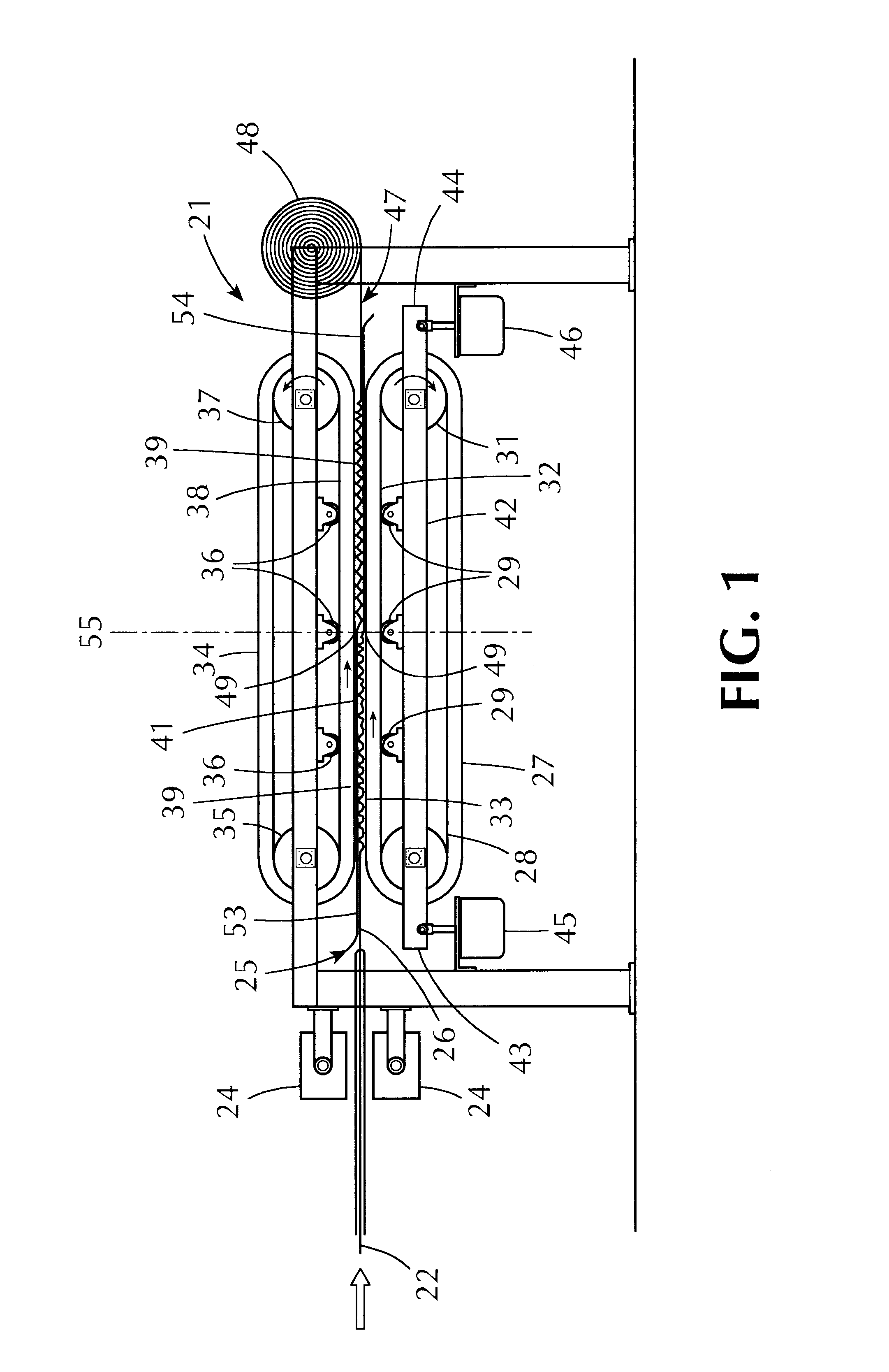
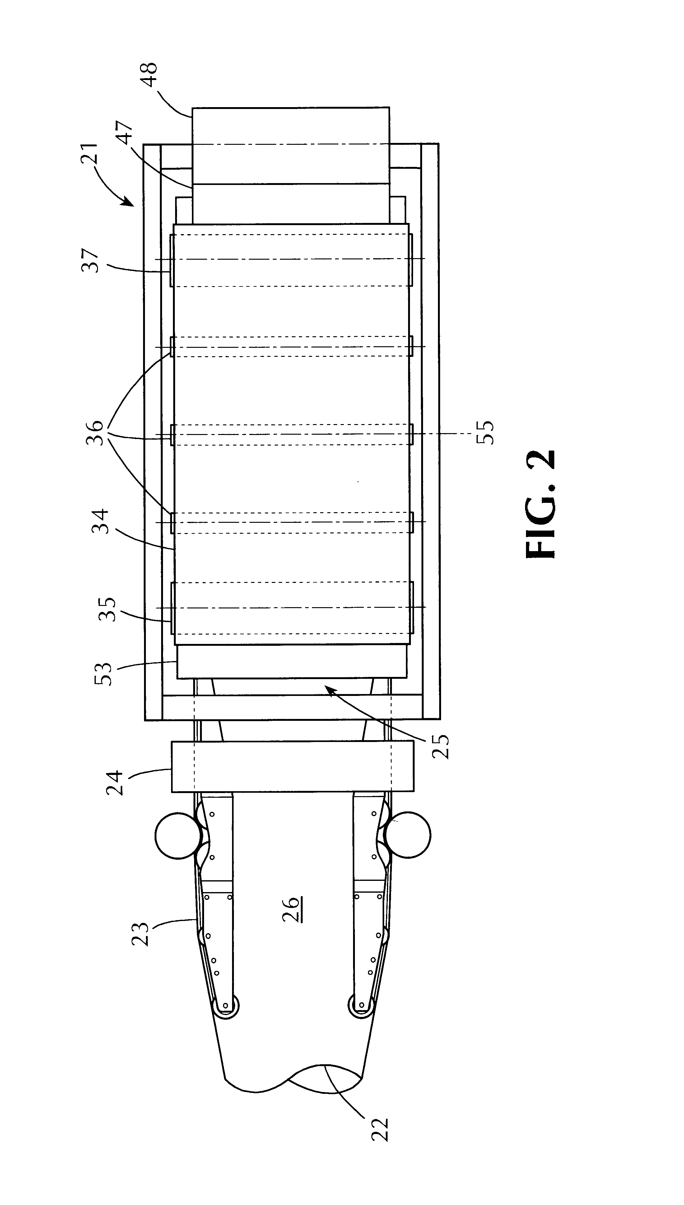
One embodiment of the present invention is shown in FIGS. 1 and 2 as a compactor generally designated 21 comprising twin endless belts. The compactor 21 treats a knitted tube of shrinkable fabric 22 delivered from a source (not shown) via a spreader 23 seen in FIG. 2. The particular fabric shown by way of an example in FIGS. 1 and 2 arrives dry so it is first heated and moistened by steam from steam chambers 24 whereby fibers of the fabric partially unravel and expand.

Entry means (generally designated 25) shown in FIGS. 1 and 2 receive a tube of the fabric 22 in a flattened double thickness onto an entry belt 27 organized for clockwise travel over an entry idler roller 28 and entry stabilizer rollers 29 by means of an entry driven roller 31. The entry belt 27 forms a straight, flat entry run 32, preferably horizontal, which presents a flat clockwise traveling entry surface 33.

Retarder means are shown in FIG. 1 as a retarder belt 34 organized for endless counterclockwise travel over ...


PUM

PropertyMeasurementUnit
Thicknessaaaaaaaaaa
Pressureaaaaaaaaaa
Shrinkageaaaaaaaaaa

Abstract

A method and related apparatus for shrink-proofing a fabric, typically a knitted textile composed of interlocked loops of yarn made of natural and / or man-made fibers. The loops interlock along stitch rows that may become skewed. According to the invention the fabric is confined from expanding as it is delivered to and discharged from an in-line compression zone free of obstructions such as crimps, bends or kinks. The fabric is confined, preferably resiliently, coming to, passing through and leaving the compression zone so as to accommodate variation of thickness and irregularities of the fabric being compacted in the compression zone. The interlocked loops are organized whereby they are allowed to move toward each other orthogonally along their related stitch row so as to reduce volume of the fabric. Non-woven textiles, papers, papers with additives and the like are shrink-proofed in the same manner.

Description

DISCUSSIONThe knitting industry uses, for manufacture of garments, various compacted knitted textile fabrics of different constructions generally accepted as having been shrink-proofed. For such compressive shrink-proofing, two-pass types of compactors have been in vogue, as disclosed in each of U.S. Pat. Nos. 4,689,862 and 5,655,275; which compactors are typical of machines used for knitted fabric made of natural and / or man-made fibers. Although these compactors produce generally acceptable shrink-proofing results, they are temperamental and require frequent re-adjusting of their compression zones.U.S. Pat. No. 5,016,329 uses two stationary opposing blades to form a compression zone. A fabric being compacted is required to change direction abruptly on entering and exiting a compression zone. Applicant's GULL-WING brand compactor, disclosed in U.S. Pat. No. 5,012,562, employs a compression zone consisting of an apex (or nadir) of a stationary notched shoe and an opposing impact blad...

Claims


Application Information

Patent Timeline
IPC IPC(8): D06C21/00
CPCD06C21/00
Inventor CATALLO, FRANK
Owner CATALLO FRANK
Learn More