Eureka AIR delivers breakthrough ideas for toughest innovation challenges, trusted by R&D personnel around the world.

On-board apparatus for avoiding restricted air space in non-overriding mode

a non-overriding mode and apparatus technology, applied in the direction of navigation instruments, process and machine control, instruments, etc., can solve the problems of component never being truly tamper-proof, achieving tamper-resistance, and realizing tamper-proo

Inactive Publication Date: 2004-01-06
TRIMBLE NAVIGATION LTD
View PDF30 Cites 161 Cited by
  • Summary
  • Abstract
  • Description
  • Claims
  • Application Information

AI Technical Summary

Benefits of technology

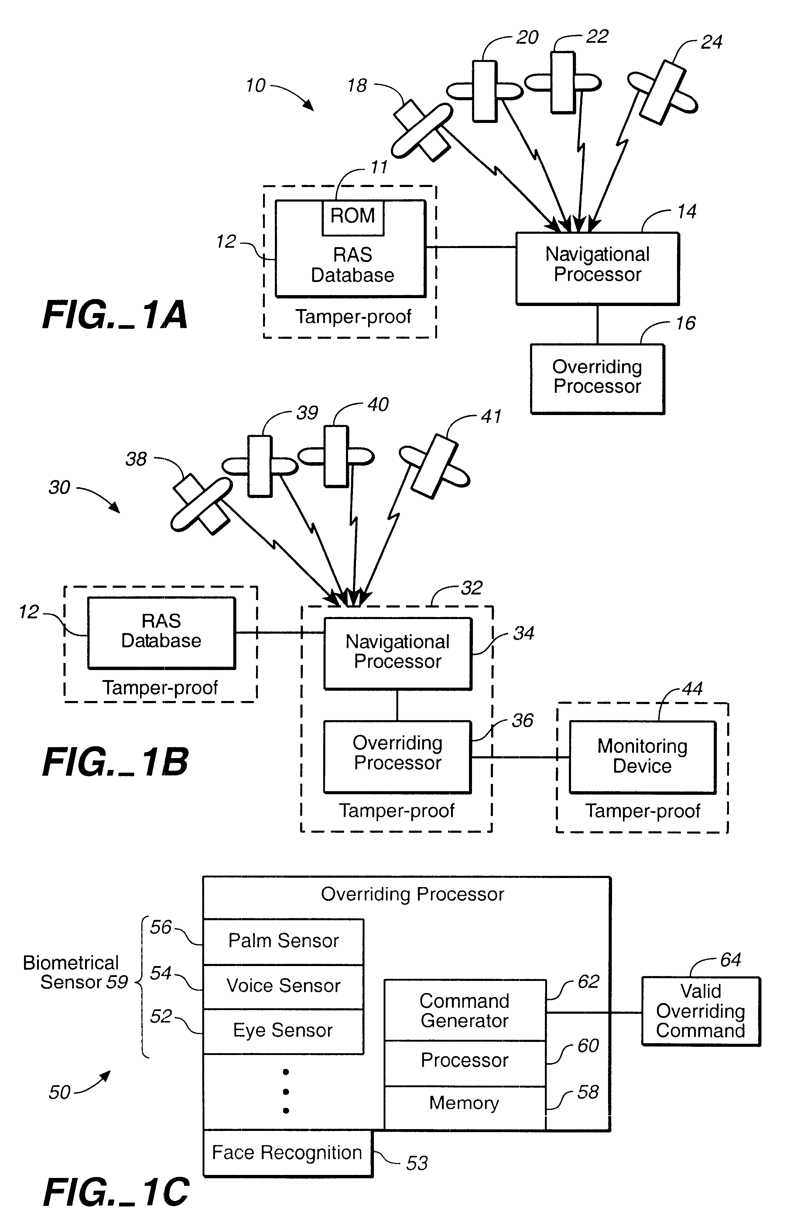
In one embodiment of the present invention, the anti-spoof and anti-jam pseudolite located in the RAS includes a split-spectrum pseudolite that is configured to substantially continuously transmit a set of real time split-spectrum pseudolite signals including the position coordinates of the pseudolite and a buffer range data set defining around the RAS. The set of split-spectrum signals is configured to minimize interference with the reception of satellite signals by the satellite receiver located on board of the aircraft.
In one embodiment, the anti-spoof and anti-jam pseudolite located in the RAS includes a split-spectrum pseudolite that is configured to substantially continuously transmit a set of real time split-spectrum pseudolite signals including the position coordinates of the pseudolite and a buffer range around the RAS. The set of split-spectrum signals is configured to minimize interference with the reception of satellite signals by the tamper-proof / tamper-resistant satellite positioning receiver located on board of the aircraft.

Problems solved by technology

Some components may be truly tamper-proof, while others can only achieve tamper-resistance.
That is, the component cannot ever be made truly tamper-proof.

Method used


Image

  • On-board apparatus for avoiding restricted air space in non-overriding mode
  • On-board apparatus for avoiding restricted air space in non-overriding mode
  • On-board apparatus for avoiding restricted air space in non-overriding mode

Examples


Embodiment Construction

.

Reference will now be made in detail to the preferred embodiments of the invention, examples of which are illustrated in the accompanying drawings. While the invention will be described in conjunction with the preferred embodiments, it will be understood that they are not intended to limit the invention to these embodiments. On the contrary, the invention is intended to cover alternatives, modifications and equivalents that may be included within the spirit and scope of the invention as defined by the appended claims. Furthermore, in the following detailed description of the present invention, numerous specific details are set forth in order to provide a thorough understanding of the present invention. However, it will be obvious to one of ordinary skill in the art that the present invention may be practiced without these specific details. In other instances, well known methods, procedures, components, and circuits have not been described in detail as not to unnecessarily obscure a...


PUM


Abstract

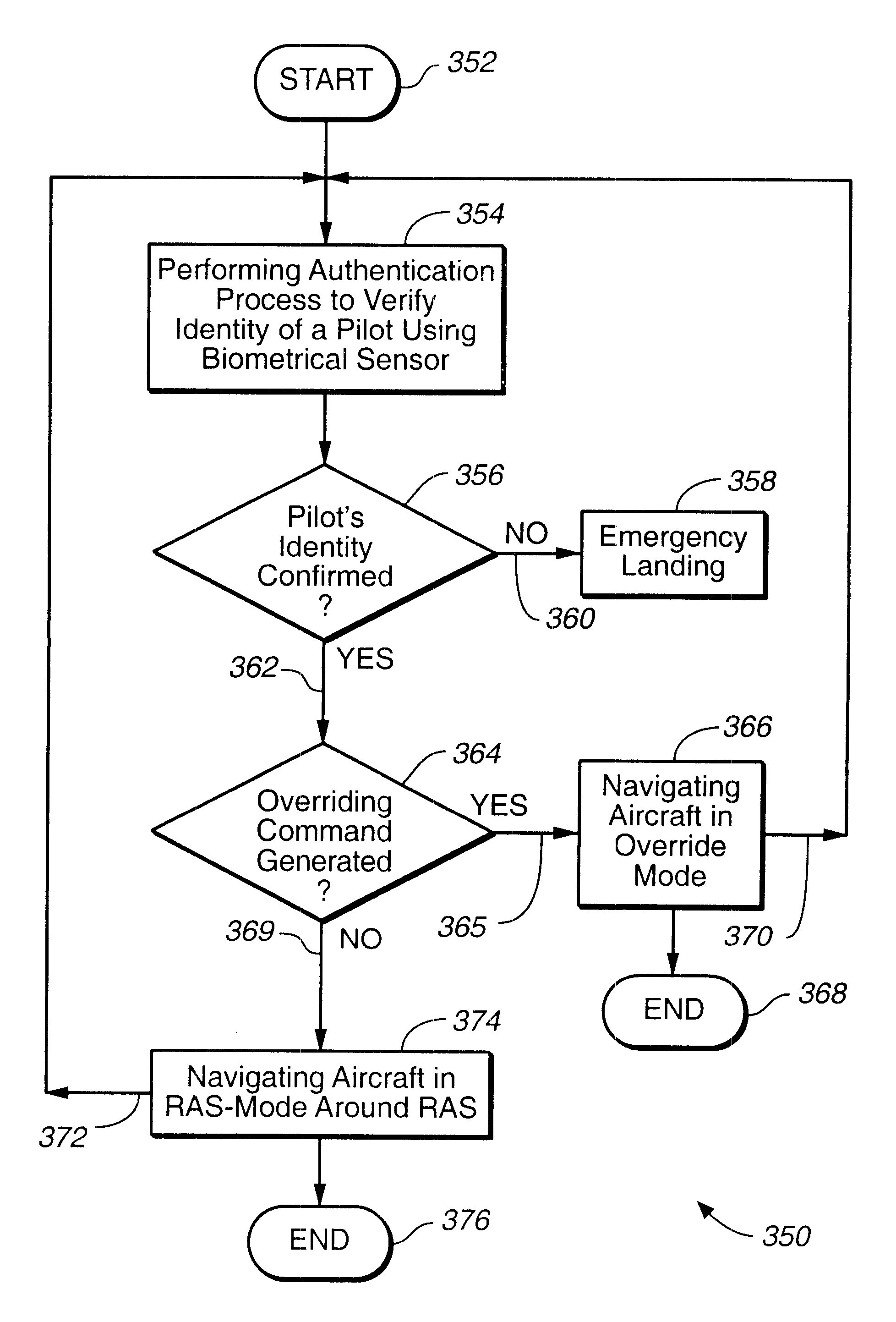
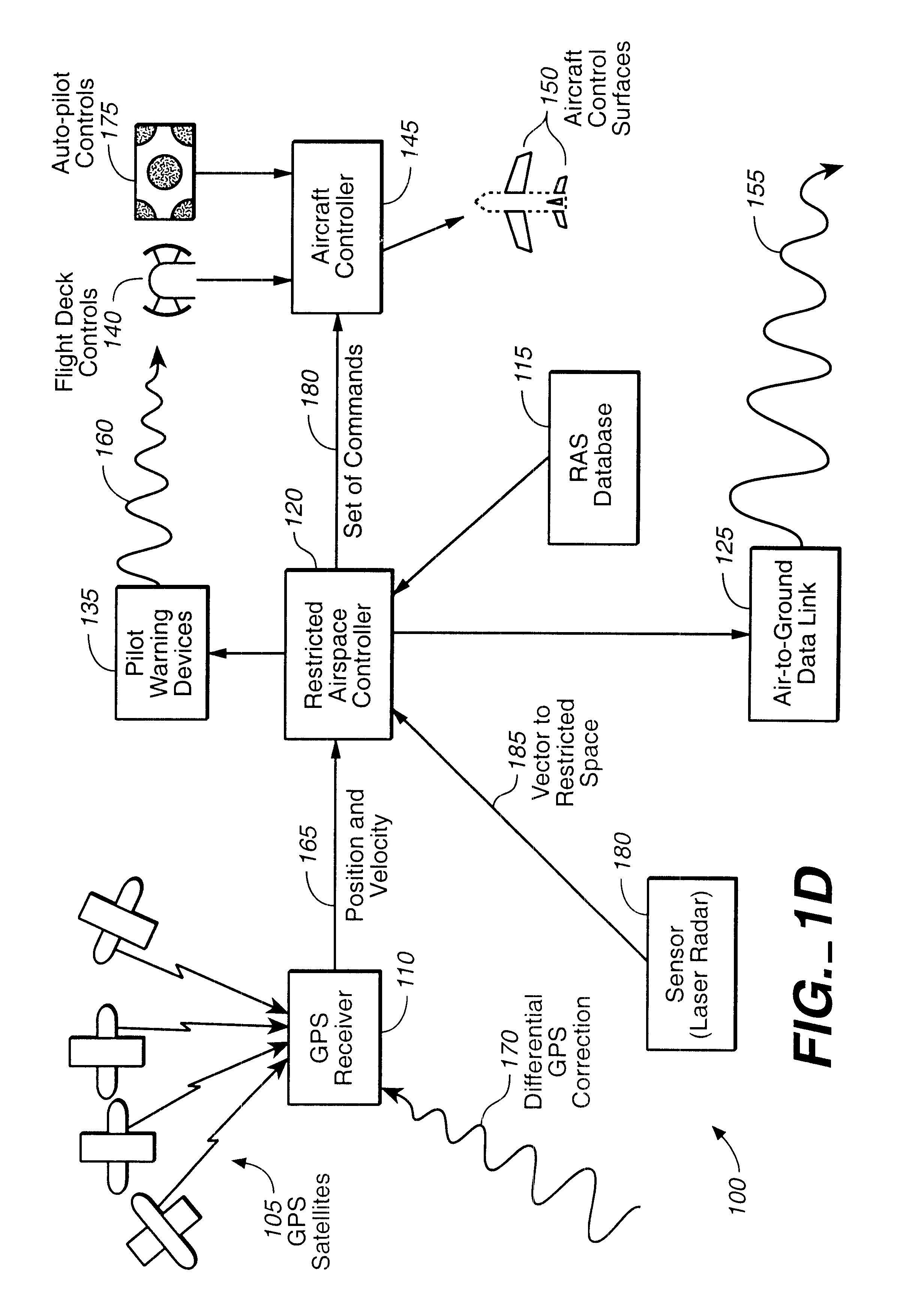
A tamper-resistant apparatus located on board of an aircraft for avoiding a restricted air space (RAS) comprising: (a) a tamper-resistant restricted air space (TAP-RAS) database configured to include a set of coordinates that determines the RAS; and (b) a navigational processor configured to navigate the aircraft around the RAS, if a valid overriding command is not generated. The navigational processor includes: a Satellite Positioning System (SATPS) configured to substantially continuously obtain a set of real time position coordinates of the aircraft; a restricted airspace controller configured to receive a set of real time data including the set of coordinates that determines the RAS, the set of real time position coordinates; and configured to analyze the set of real time data in order to substantially continuously generate a set of real time commands; and an aircraft controller configured to navigate the aircraft utilizing the real time set of commands around the RAS. The navigational processor is configured to navigate the aircraft in an overriding mode, if the valid overriding command is generated.

Description

1. Field of the InventionThe present invention relates to a field of collision avoidance systems, and more specifically, to a field of navigating an aircraft around a restricted air space (RAS).2. Discussion of the Prior ArtMany commercial aircraft systems include avionics systems that prevent the pilot from instructing the plane to do maneuvers that are outside of its design envelope. For instance, Krumes et al in the U. S. Pat. No. 5,465,142, discloses "a system for sensing objects in the flight path of an aircraft and alerting the pilot to their presence including a laser radar subsystem for emitting a beam of laser energy, receiving returns from objects, and processing the returns to produce range data related to the range of the objects from the aircraft. A scanning subsystem scans the beam and produces directional information related to the instantaneous direction of the beam relative to the aircraft. Processor circuitry controls operation, processes the range data and directi...

Claims


Application Information

Patent Timeline
Patent Type & Authority Patents(United States)
IPC IPC(8): G05D1/00G01S19/48
CPCG05D1/0061B64D2045/0055B64D45/0031B64D45/0059
Inventor BIRD, DAVID GLENNJANKY, JAMES M.
Owner TRIMBLE NAVIGATION LTD
Why Eureka
Eureka Blog
Learn More