Eureka AIR delivers breakthrough ideas for toughest innovation challenges, trusted by R&D personnel around the world.

Jack-up platform comprising a deck structure and a single supporting column, and method for installing such jack-up platform

Inactive Publication Date: 2003-11-18
GUSTOMSC RESOURCES BV
View PDF8 Cites 6 Cited by
  • Summary
  • Abstract
  • Description
  • Claims
  • Application Information

AI Technical Summary

Benefits of technology

is to provide a jack-up platform which meets the above incompatible requirements but which, at the same time, is relatively rapid and simple to install and move, even in great water depths.
To increase the floating power of the jack-up platform when towing it to the desired location, it may be provided that at least the base or at least one of the base supporting parts comprises a body with floating power, such as a tank. In the operative position of the jack-up platform such a body can further be advantageously used for all kinds of storage and transshipment purposes.
Also, according to a further embodiment of the invention, it may be preferred that the base structure can be pulled up into a suitable hole provided in the deck structure, which can reduce the traveling resistance during the conveyance of the jack-up platform to the installation site. In this case it will further often be preferred that the base structure is vertically of relatively flat design so that the height of the deck structure, in its totality, can also remain relatively low.
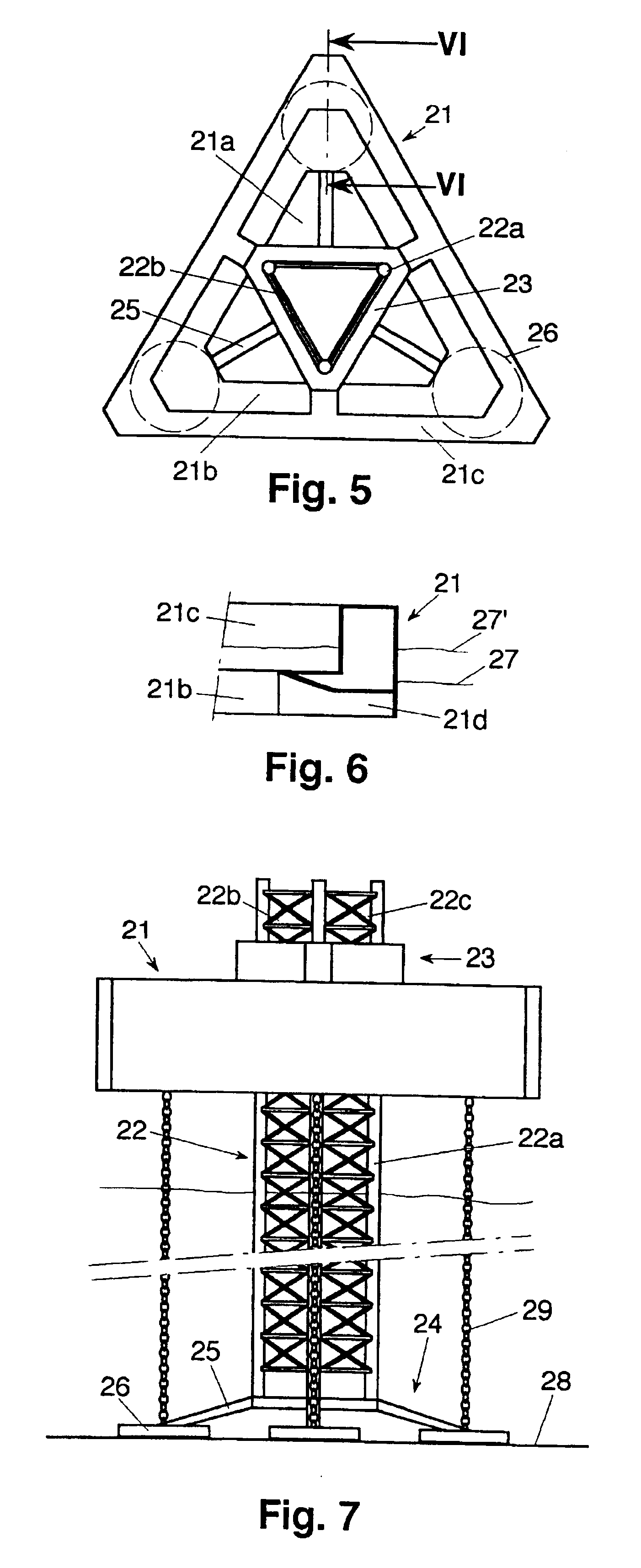
If according to a further embodiment of the invention the deck structure is composed of a lower part and an upper part, the upper part receding relative to the lower part over at least part of the circumference, the jack-up platform can be partly sunk in the manner of a semi-submersible, that is to say sunk so far that the broader lower part is under the water surface and the narrower upper part at least partly above. Thus the jack-up platform can be made more independent of wave motion when lowering the column and bringing the base structure into contact with the floor. This effect can further be optimized if the deck structure consists of an edge body surrounding a central through hole, in which hole the jack-up system is centrally and locally installed. It is further preferred that the receding part of the upper part adjoins the central through hole. Over the entire height of the deck structure the exterior of the jack-up platform may have a form adjusted to a minimum traveling resistance.
To be able to carry out the provision of the tensioning means in a relatively simple manner, that is to say without many underwater operations, in particular in greater depths, it may be preferred according to a further embodiment of the invention that the tensioning means are fixed from the deck structure in the connecting places before the column is brought downward and, via the base structure, into supporting contact with the floor. If desired, the tensioning means may also be continuously fixed in the connecting places.
To keep the required navigable depth for the jack-up platform as low as possible during transport to the site where it needs to be installed, it may further be preferred that, when bringing the platform to the desired location, the column is pulled up so far that the base structure is in the immediate vicinity of the floating deck structure, which position can be realized with the jack-up system in a simple manner. To even further reduce the water resistance experienced during traveling, it is preferred that the column is pulled up so far that the base structure is completely within a space provided in the deck structure for this purpose.

Problems solved by technology

The provision of such guylines, however, is an extremely difficult and labor-intensive, if not, in particular in great depths, practically impossible activity.
Under the circumstances it will not always be possible that the base supporting parts are supported on a flat horizontal surface.

Method used


Image

  • Jack-up platform comprising a deck structure and a single supporting column, and method for installing such jack-up platform
  • Jack-up platform comprising a deck structure and a single supporting column, and method for installing such jack-up platform
  • Jack-up platform comprising a deck structure and a single supporting column, and method for installing such jack-up platform

Examples


Embodiment Construction

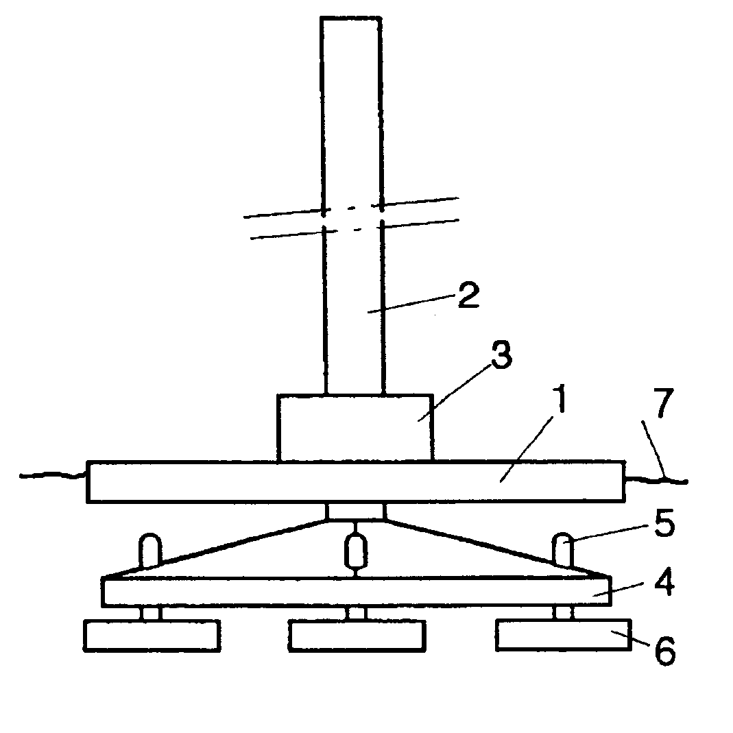
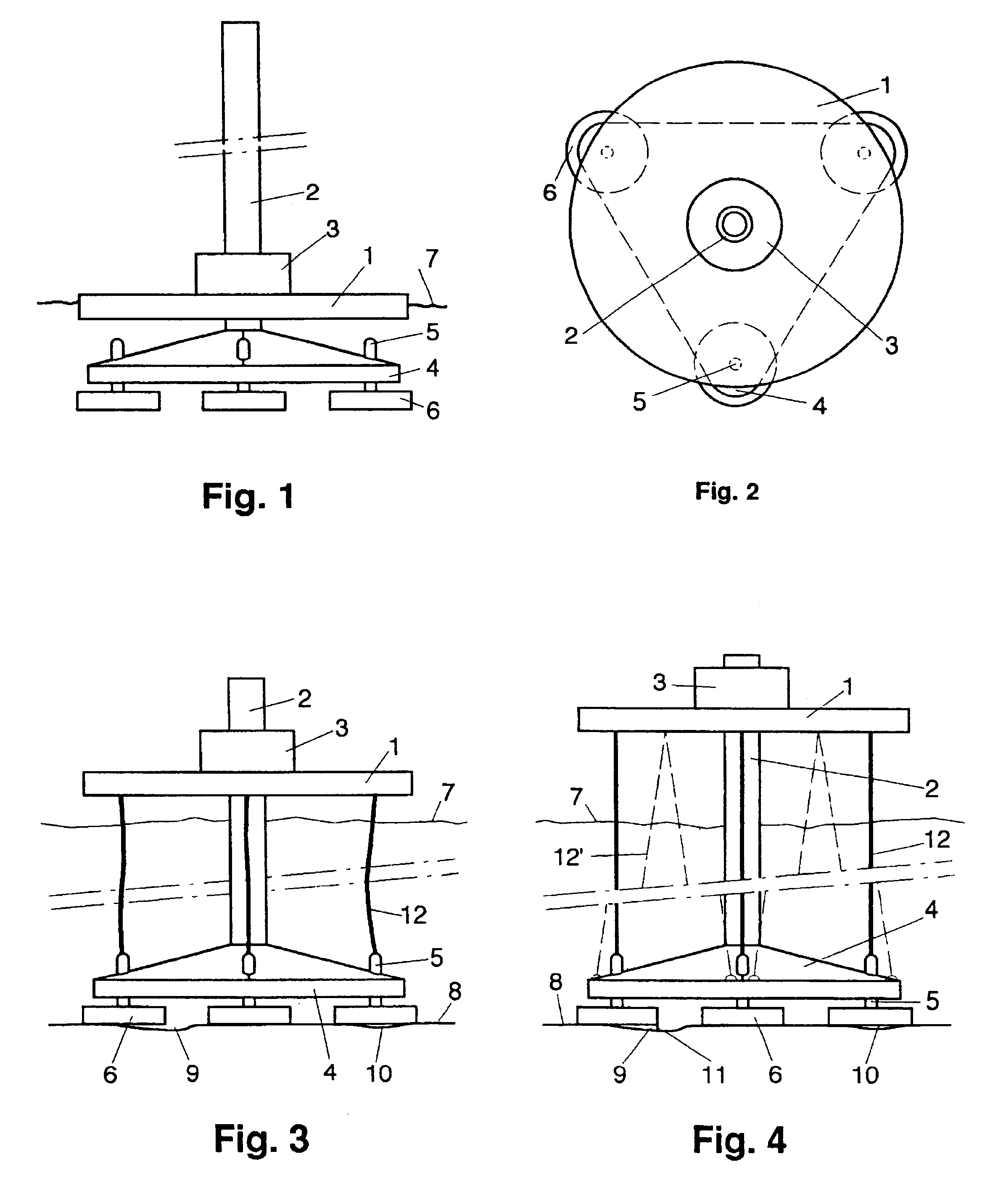
The jack-up platform shown in FIGS. 1 and 2 comprises a substantially disk-shaped deck structure 1 with floating power, which deck structure is provided with a through opening for longitudinally and slidably taking up a column 2, which is slidable and securable with respect to the deck structure 1 by means of a jack-up system 3. Attached to the lower end of the column 2 is a base 4 having a substantially pyramidal configuration with three angular points, which base 4, near each angular point, carries a base supporting part 6 via a rod part 5 extending through the base 4.

FIG. 1 shows the jack-up platform in a position floating in a water with a surface 7. In this position the column 2 is raised by means of the jack-up system 3 so far that the base 4 is situated at a short distance below the deck structure 1. Thus the jack-up platform can be towed at its shallowest draft to the position where it needs to be installed. Moreover, in this position the traveling resistance is lowest.

Arriv...


PUM


Abstract

A jack-up platform comprising a deck structure, a column with a base structure and a jack-up system for moving the column and the deck structure relative to each other. The base structure comprises a base and at least three base supporting parts, while the deck structure, starting from at least three spaced coupling places, can be connected by a tensioning apparatus with at least three mutually spaced connecting places on or near the base supporting parts. Before the installation the platform, floating with pulled-up column, is brought to the desired location where the base supporting parts are brought into contact with the floor and the deck structure is raised out of contact with the water. After providing the tensioning apparatus and bringing the deck structure to working height, the tensioning apparatus is tensioned, for instance by slightly further raising the deck structure which is then secured relative to the column.

Description

This application is the National Phase of International Application PCT / NL01 / 00035 filed Jan. 18, 2001 which designated the U.S. and which International Application was published under PCT Article 21(2) in English.BACKGROUND OF INVENTION1. Field of the InventionThe invention relates to a jack-up platform comprising a deck structure with floating power and a column with a base structure, in which a jack-up system acts on the column so as to be able to move and secure the deck structure and the column relative to each other, and the base structure comprises a base and at least three separate base supporting parts. The invention also relates to a method for installing such a jack-up platform.2. Background of Related ArtSuch a jack-up platform is known from WO-A-81 / 000423. Initially, such jack-up platforms were used in relatively shallow water, but in the course of time the use also shifted to increasingly deeper water, for which water depths of 300 meters and more may be considered. Ev...

Claims


Application Information

Patent Timeline
IPC IPC(8): E02B17/02E02B17/00
CPCE02B17/021E02B2017/0056E02B2017/0086E02B2017/0082E02B2017/006
Inventor MOMMAAS, CORNELIS J.MANSCHOT, DIRK
Owner GUSTOMSC RESOURCES BV
Why Eureka
Eureka Blog
Learn More