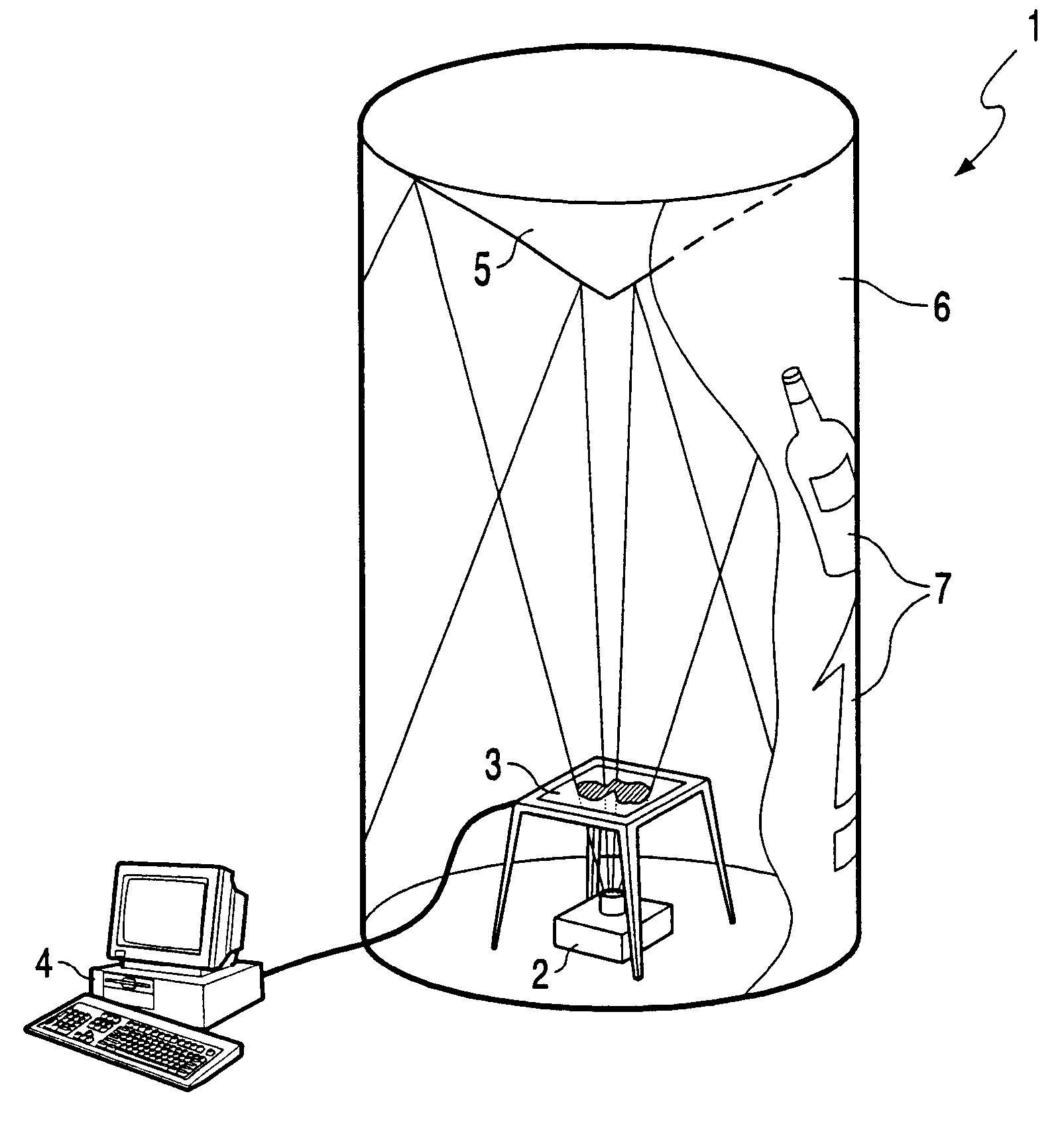
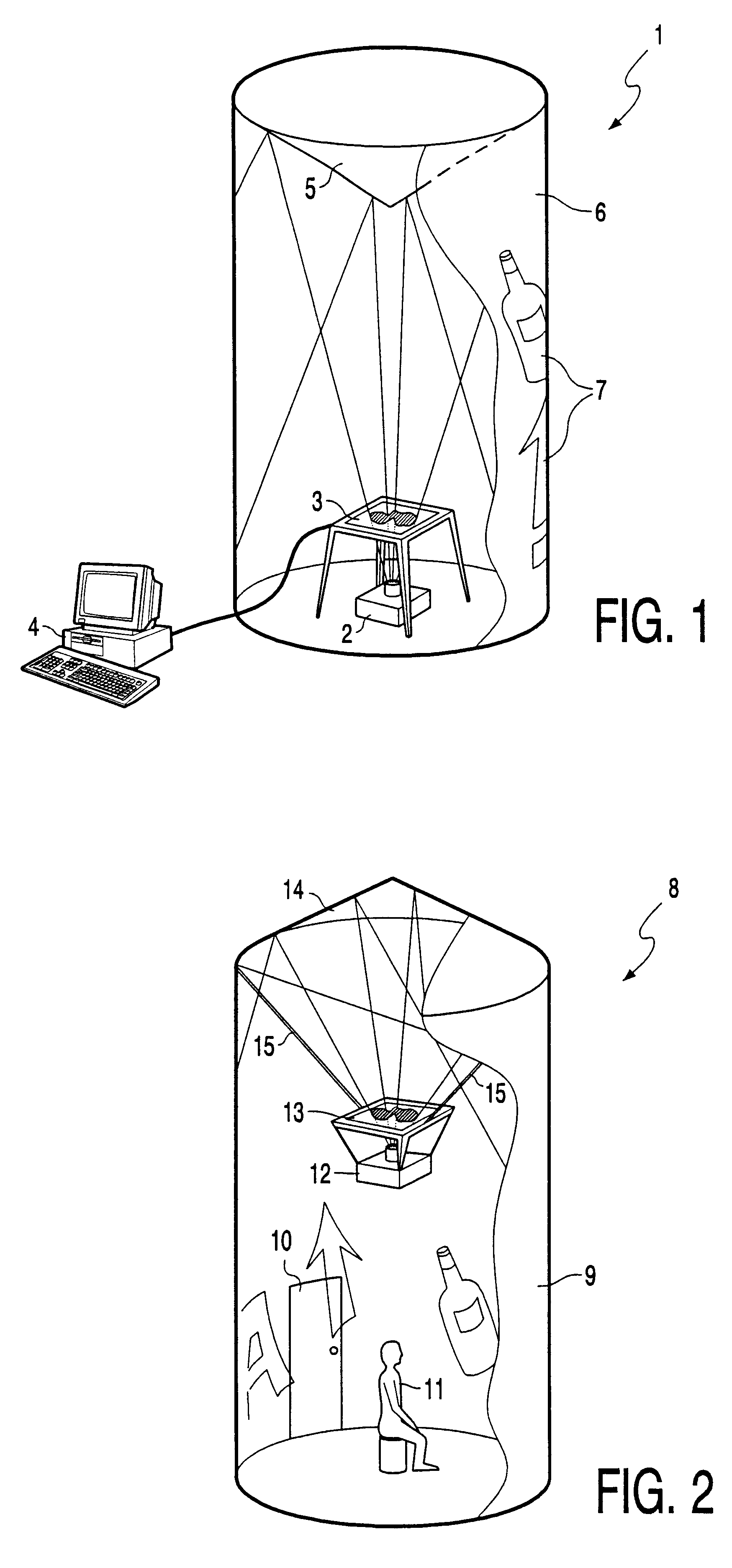
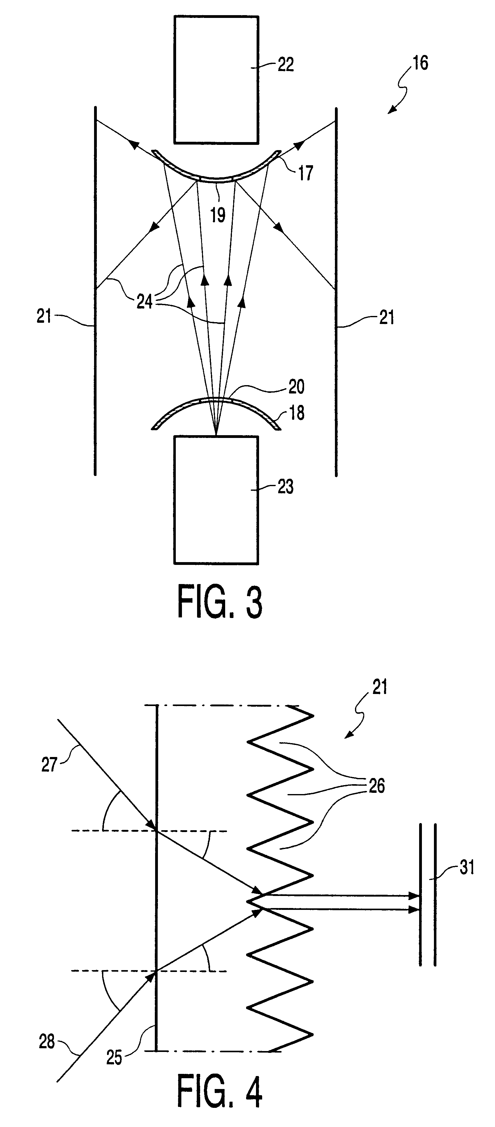
The invention provides for this purpose a
display device for displaying visual information. The optical means preferably comprise at least a reflector which can take the form of at least a part of a
conical surface or a
pyramid. In addition, it is also possible to use an
intermediate form of cone and
pyramid, for instance a polygon. With such a display device an illuminated image can be displayed on a continuous way in a random size on a projection surface which has a curved shape of a cylinder shell. The continuous cylindrical projection of the image on the projection surface makes the image steady and more clear then when each part of the projection surface is lighted during only a period of time. Another
advantage in relation to the projection device as disclosed in the German Gebrauchsmuster is that the device according the invention has no mechanically
moving parts; this makes the device according the invention better in use (less noisy), more reliable and less liable of maintenance. Another
advantage of such a projection surface is that it produces a very attractive appearance for a wide variety of applications, and not only for adjustment to a ceiling, such as for instance advertising pillars, video conferencing displays,
virtual reality pillars etc. It is noted herein that as desired the inside or the outside is considered as the primary projection surface. In said application as advertising pillar, for instance at large events, fairs, in shopping centres, at stadiums and airports, particularly the outside of a pillar is the relevant projection surface. In an application as
virtual reality pillar, use can in contrast be made of the inside of the cylinder wall as projection surface so that a person at least partially surrounded by the cylinder wall surface can undergo the illusion of being in a different environment. An additional option here can consist of embodying, at least a part of the projection surface as so-called `touch screen`, whereby the projected visual information can be changed by touching said screens. Owing to the entirely new concept of displaying visual information such as picture material with the display device according to the invention, many applications will become possible which do not exist at the moment. By embodying the optical means in the form of a reflector, the costs thereof can be limited. With a reflector in the shape of a cone or
pyramid a simple construction can moreover be realized in combination with the cylinder wall-shaped projection surface. An additional
advantage herein is that with said reflector shapes the
distortion of the image created by the image-forming element is controllable.
In another preferred embodiment the image-forming element is coupled to a computer for control thereof. The control of the image-forming element enables changing of the projected images as desired. It is thus possible to adapt the visual information to an actual situation. It is also possible to display moving images with the image-forming element. Yet another option of the computerized control is the possibility of compensating the image created by the image-forming element on the optical means When the
distortion of the optical means is known, it is possible by means of a standardized process to control the image-forming element such that the projected image acquires the desired form, The
distortion of the optical means can thus be compensated by means of a standardized conversion. Yet another advantage of the control by means of computer is that the computer can be programmed by means of cables or a remote
receiver such that the desired images are projected. Changing of the images for displaying can thus take place at a distance and makes it unnecessary to go to the display device.
In a preferred embodiment the image-forming element is formed by a light passage screen, such as for instance a display with liquid crystals, also referred to as
liquid crystal display (L.C.D.). A variant hereof is referred to as ferro liquid display (F.L.D.). Such a light passage screen is preferably disposed between the
light source and the optical means. Such a light passage screen is affordable and obtainable in both black-and-white and colour versions. The display device can be constructed very simply when the
light source, for instance a
projector, casts a
light beam through the light passage screen whereby an illuminated image results which is subsequently directed onto the projection surface by the optical means. Such a display device can be manufactured for a significant part with components which are readily available. In practice the light passage screen will usually be placed in the
projector so that it is situated between the light source and the lens of the
projector. This solution is moreover compact and easy to install.
The projection surface is preferably manufactured from a transparent material such that an image projected on the inside of the cylinder wall is visible on the outside of the cylinder wall. The image-forming element, the light source and the optical means are herein preferably all disposed substantially in the cylinder defined by the projection surface. Such a display device can be embodied such that the outside is cylindrical without associated components situated on the outside of the cylinder. This provides the display device with an aesthetically attractive appearance and enables use of the display device in a variety of environments. Depending on the choice of material for the cylinder wall and / or the arranging of a protective casing, the display device is vandal-proof. An additional advantage is that the projection means in such a display device take up no space outside the cylinder, which also increases the application possibilities.


