
Multiple display portable computing devices

a portable computing and display technology, applied in the field of multi-display portable computing devices, can solve the problems of reducing the volume requirement, rejecting display devices, and not linear in surface area of flat display pricing, so as to reduce the volume requirement, and manufacture more thinly.

Inactive Publication Date: 2003-11-04
WILK PETER J
View PDF25 Cites 432 Cited by
  • Summary
  • Abstract
  • Description
  • Claims
  • Application Information

AI Technical Summary

Benefits of technology

Third, multiple display panels of a total effective surface area equivalent to that of a large single panel generally present information more effectively and attractively than a single display. A window of 1 / 3 the total area of a single display has linear dimensions 0.577 of those of the parent display. There is no way to tile three such windows of the same aspect ratio as a parent screen on the parent, and centering a single such window leaves a border of less than 1 / 4 of the original screen dimensions, which is difficult to effectively use for the display of information. Information on a single screen is also more difficult to visually differentiate than when presented on multiple adjacent displays and results more quickly in eye fatigue when repeatedly shifting attention between windows, as the eye may lack sufficient cues to enable an effortless shifting of attention.
Fifth, multiple displays allow an adaptation of display type to intended function, with a consequent cost reduction. A multiple display device may provide a single high-resolution color display panel for viewing of digital images and one or more less expensive monochromatic displays for data and word processing. Lower resolution may also be comfortably accepted in a display intended only to present legible alphanumeric characters rather than color or gray scale images. A text-only screen may also take advantage of simplified and hence faster video drivers. In general, an economic principle of division of labor is tapped by adapting device capabilities to function rather than providing a sufficient amount of a highest priced and most versatile resource to cover all required functions.
Use of half-width sliding wing panels results in smaller net screen area for given dimensions of a central display, but has an advantage that the side panels may be selectively deployed as needed in tight spaces. Full width sliding wing panels may also be employed, at a price of a thicker case element or central panel, or employment of more technically advanced thin displays.
Flexible display screens may also be used as components of multiple display computing devices according to the present invention. A flexible video or display screen may be rolled up in a storage configuration and unrolled and stretched flat by a frame in a usage configuration. Lacking a requirement of rigidity, a flexible screen may be manufactured more thinly, and hence of reduced volume, relative to a rigid display panel. Flexible displays therefore reduce a volume requirement of a compactly folded unit. A flexible screen may in fact be the only way to obtain a given contiguous deployed display area on a small device, such as a cellular phone. Current cellular phone display panels are limited to a few lines of 40 character resolution or less. By combining at least one display in the megapixel range with a hand-held transceiver, cellular phones may fulfill their promise as wireless voice actuated portals to the Internet.

Problems solved by technology

First of all, flat display pricing is not linear in surface area.
Manufacturing defects are more likely to result in rejected display devices the larger a surface area of the device.
If a particular manufacturing technology results in 50% of all display panels of area A being discarded at the factory, then a simple scaling of the identical manufacturing technique to panels of area 2A is expected to result in rejection of 75% of the panels.

Method used


Image

  • Multiple display portable computing devices
  • Multiple display portable computing devices
  • Multiple display portable computing devices

Examples


Embodiment Construction

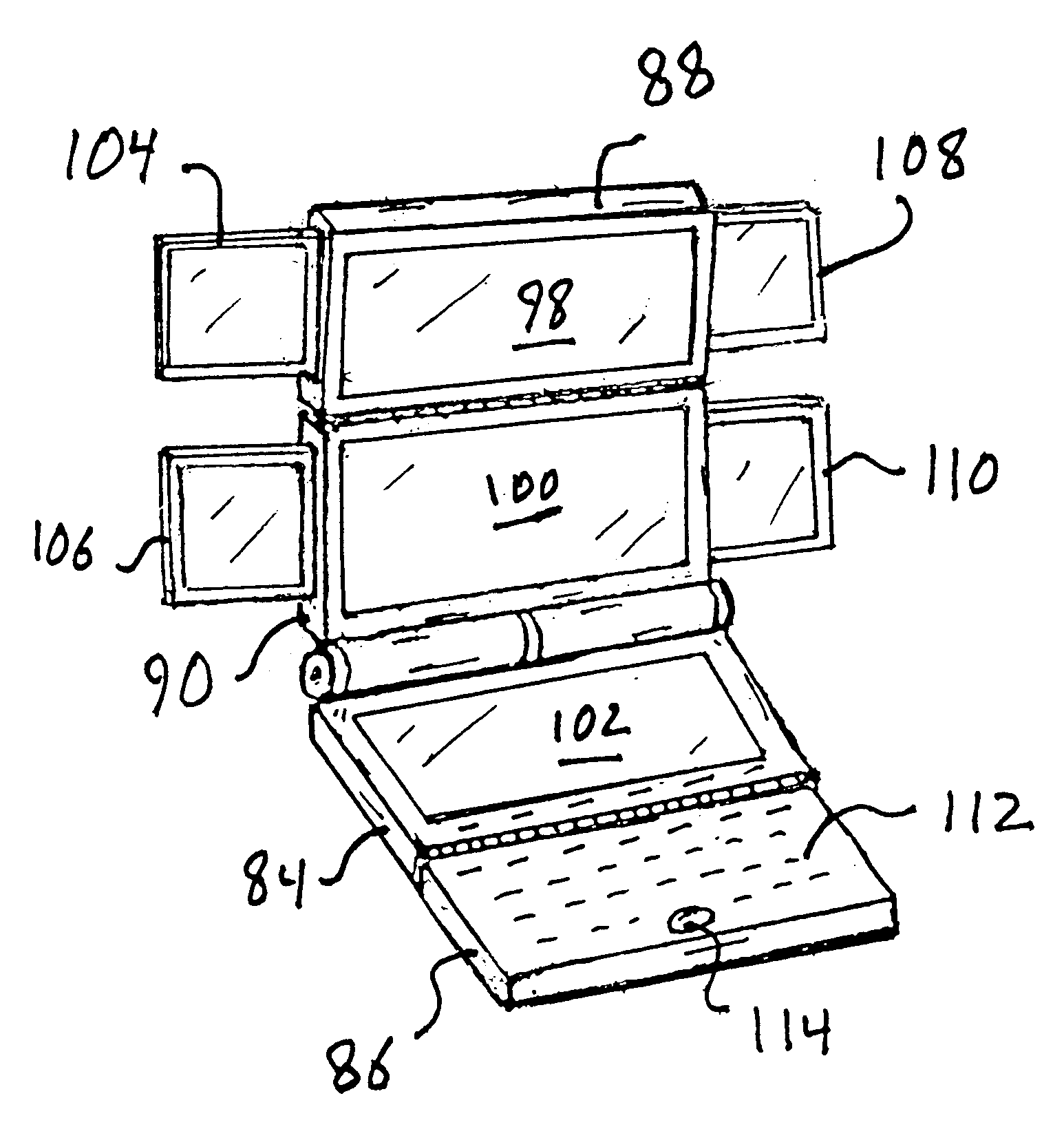
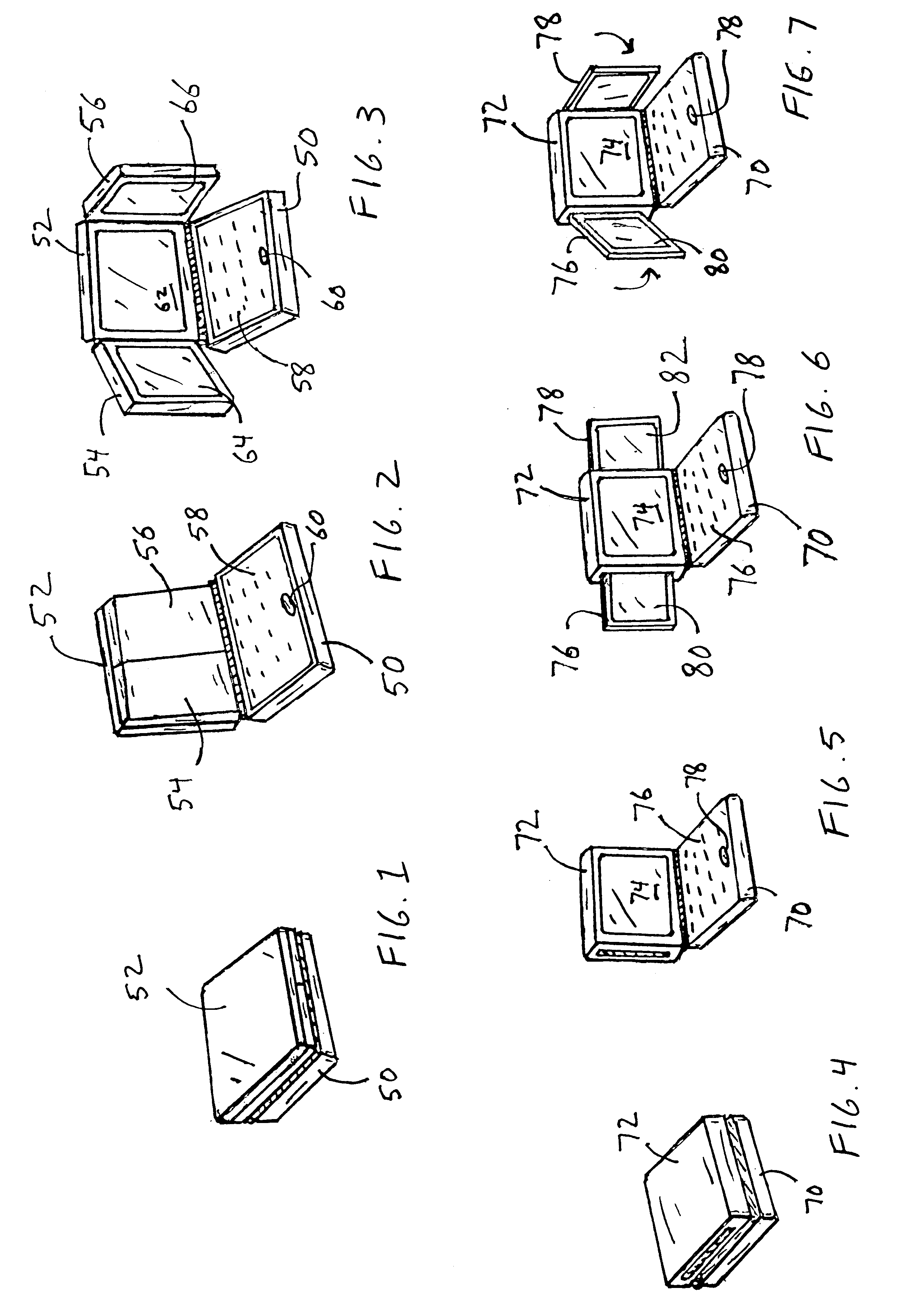
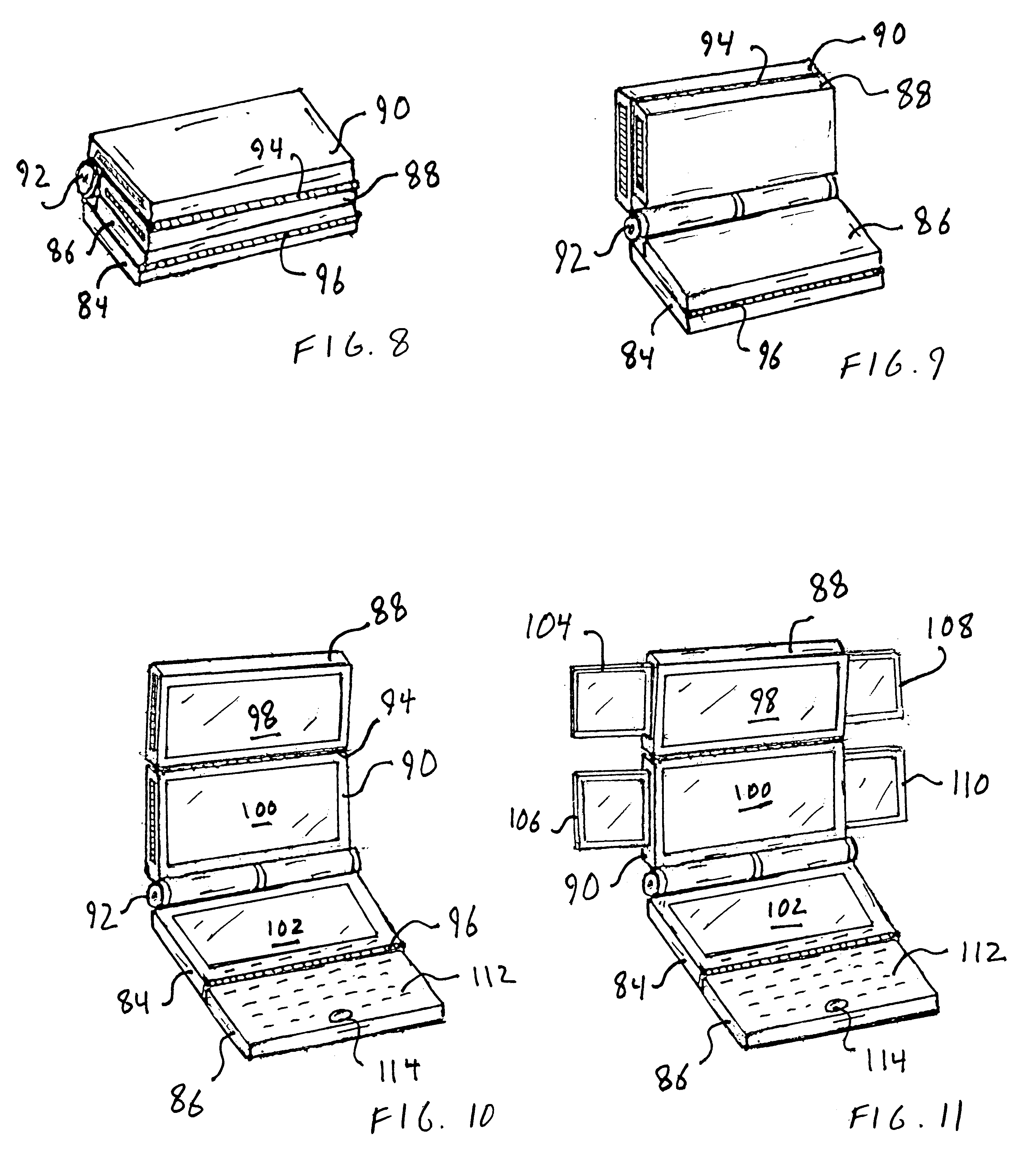
A portable personal computer or computing device is generally shown in FIG. 1 in a folded or compact configuration, showing combined functional panels (as defined above) and case elements 50, 52. The portable computing device of FIG. 1 is shown in a partially unfolded or deployed configuration in FIG. 2. Case element 50 is an input panel, with keyboard 58 and trackball 60, while case element 52 is overlaid on an inside surface (not designated) by additional internal case elements or functional panels 54, 56. In FIG. 3, the portable computer of FIGS. 1 and 2 is shown in a fully unfolded or deployed configuration, revealing case elements 52, 54 and 56 to be output panels respectively provided with flat screens 62, 64 and 66. Panels 52, 54 and 56 constitute a triptych, or three paneled foldable device, with a compact configuration protecting sensitive inner surfaces, in this case represented by screens or flat displays 62, 64, 66. Panels 54, 56 form auxiliary panels or wings, joined fo...


PUM


Abstract

A portable computing device is equipped with multiple display panels. The display panels and hinged, jointed or otherwise disposed to rotate or slide with respect to one another in a transition from a compact configuration to an expanded configuration. In a basic embodiment three output screens take a form of a triptych for which an input panel forms a base. The output panels are deployed with a bend when opened and images angled in towards an observer. The display panels comprise a main panel and two auxiliary panels. In a variation a forth display panel is rotatably or foldably joined to the central display panel so that a total of four display panels may be deployed in a hub and petal configuration. The side panels may be eliminated from the four panel embodiment so that the input panel and two remaining display panels form a vertically orientable triptych with the input panel serving as base.

Description

This invention relates to computing devices. In particular, this invention relates portable computing devices, and to computer output display devices.1. Baclground of the InventionPersonal computers have made huge strides in processor speed and static and dynamic memory costs in the last decade. Computer display technology however, while enjoying incremental improvements and a gradual decline in price, has not yet followed suit. Large high quality flat screen displays remain prohibitively expensive to manufacture because of residual manufacturing defect concentration and a simple mathematical relation which makes a mean number of expected defects per screen proportional to an area of that screen, meaning that a chance of manufacturing a defect-free display steadily declines with an area of that display. Large area CRT displays are less expensive, though still not having declined in cost in proportion to other computer resources, but are also bulky and occupy a volume which grows rou...

Claims


Application Information

Patent Timeline
Patent Type & Authority Patents(United States)
IPC IPC(8): G06F1/16H04M1/02
CPCG06F1/1616G06F1/1626G06F1/1647H04M1/0247G06F1/1652H04M2250/16H04M1/0214H04M1/0235
Inventor WILK, PETER J.
Owner WILK PETER J
Learn More