
Crossbar switch and control for data networks switching

a technology of data network switching and crossbar switch, which is applied in the direction of data switching network, frequency-division multiplex, instruments, etc., can solve the problem that the assumption is no longer valid

Inactive Publication Date: 2003-10-21
ROUND ROCK RES LLC
View PDF18 Cites 116 Cited by
  • Summary
  • Abstract
  • Description
  • Claims
  • Application Information

AI Technical Summary

Problems solved by technology

As the bandwidths of the signals which are routed through such devices increases, such assumption is no longer valid.

Method used


Image

  • Crossbar switch and control for data networks switching
  • Crossbar switch and control for data networks switching
  • Crossbar switch and control for data networks switching

Examples


Embodiment Construction

A block diagram of a one embodiment for the crossbar switch is shown in FIG. 8. Serial high-speed data (7) enters the input synchronizer (1) which includes two major blocks. First a phase synchronizer (10) aligns the incoming data stream with the internal high-speed clock to insure perfect clock versus data timing in the subsequent flip-flops. FIG. 10 shows the details of the phase synchronizer (10) and its associated phase control (13). The incoming data (34), which corresponds to data (7) shown in FIG. 8, is transferred through the programmable delay line (30)shown in FIG. 10 at the output of which its transitions phase (timing) is compared with the transition timing of the high-speed clock (9) using the phase detector (31). The output of the phase detector (31) is transferred via a low-pass filter (32) in order to eliminate any short term glitches, and controls the up / down counter (33). The programmable delay is adjusted to delay the incoming data stream such that transitions of ...


PUM


Abstract

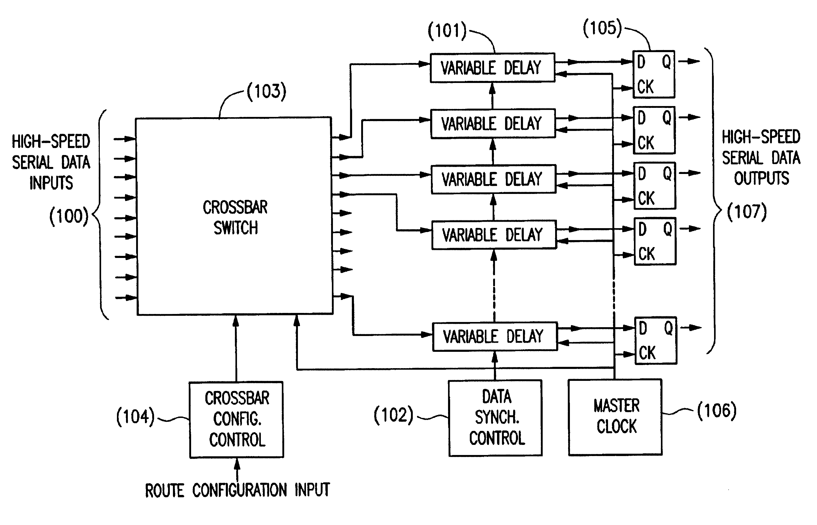
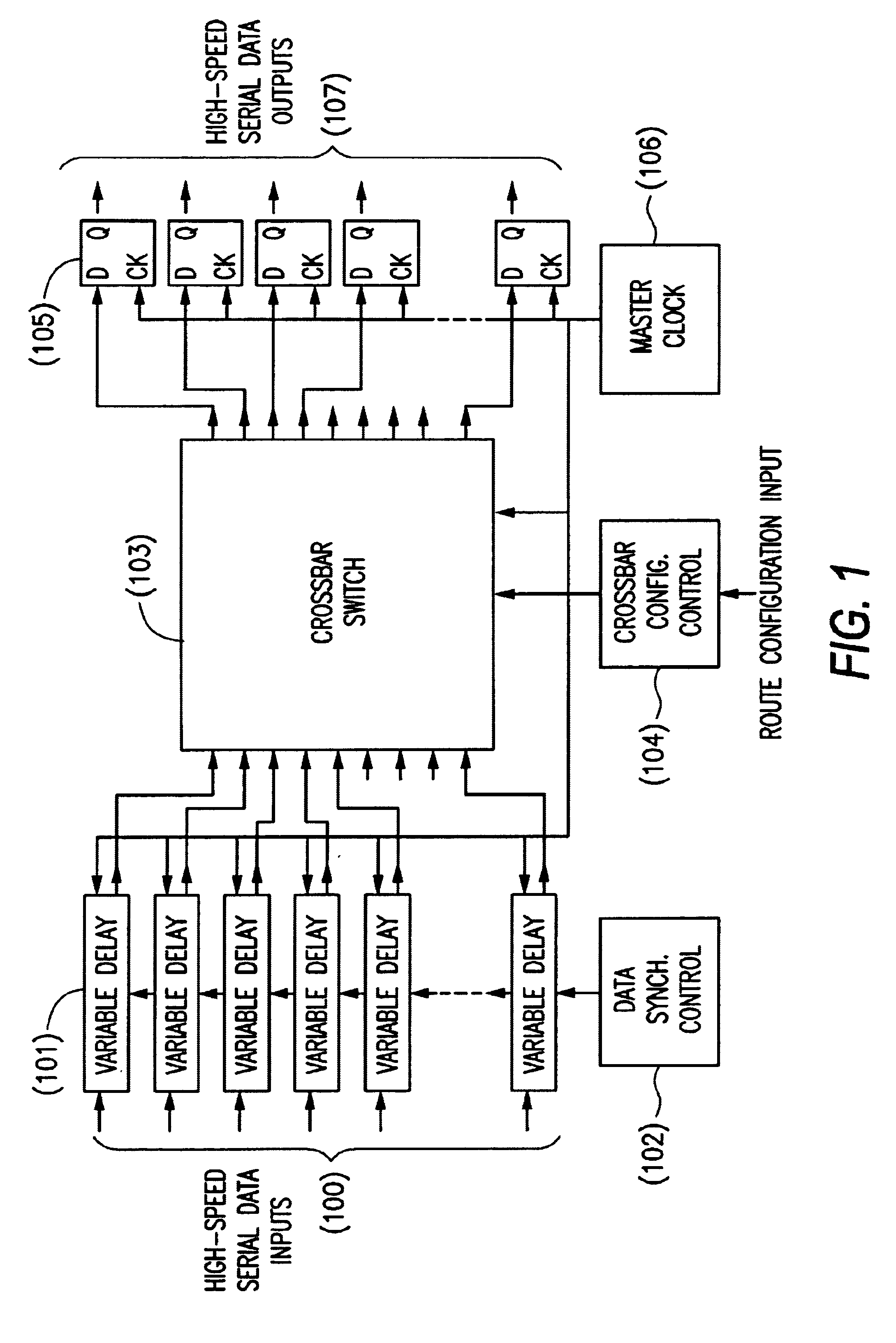
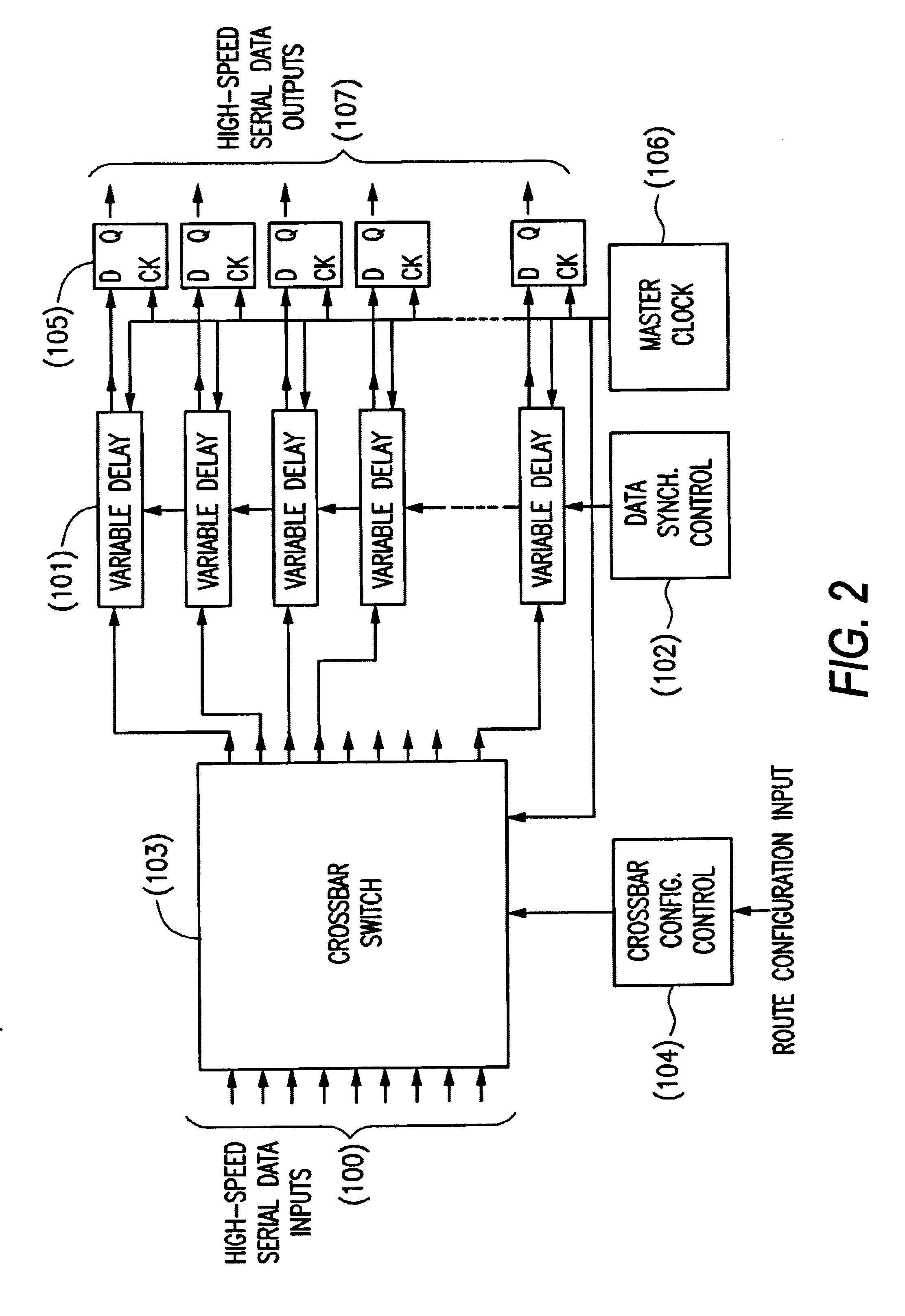
A modified version of a switching / routing device commonly known as a crossbar switch which is optimized to switch and reroute very high speed synchronous data communication signals without interruptions and / or excessive transition time shifts.

Description

In data networks, signals are normally transmitted in an encoded format and receivers use Phase Locked Loops (PLL) to recover the clocks and data from the received signals. In network communication systems, data is transmitted in packets of different formats, with certain gaps between the packets. If special precautions are not taken, every time a packet ends the Phase Locked Loops on that network go out of lock. A significant length of time will elapse before the phase-lock is reacquired. Such gaps in data transmission greatly increase the latency through the system, and reduce the system capability of transferring certain types of data streams such as Digital Video signals. To guarantee that the PLLs are kept in the phase-locked state and all times, an IDLE signal is transmitted between data packets which keep these phase locked loops in the desired locked state. However, when a signal path through a crossbar switch is changed, so does the propagation delay through the path in the...

Claims


Application Information

Patent Timeline
IPC IPC(8): H04L12/56G01R31/08G06F13/00
CPCH04L49/101H04L45/60
Inventor REGEV, ZVIREGEV, ALON
Owner ROUND ROCK RES LLC
Learn More