
Marine vessel

a watercraft and variable hull technology, applied in the direction of rafts, vessel auxiliaries, vessel construction, etc., can solve the problem that the prior art does not show how movable parts of the boat structure may be used to capture and conver

Inactive Publication Date: 2003-09-16
SYFRITT HAROLD A
View PDF6 Cites 40 Cited by
  • Summary
  • Abstract
  • Description
  • Claims
  • Application Information

AI Technical Summary

Benefits of technology

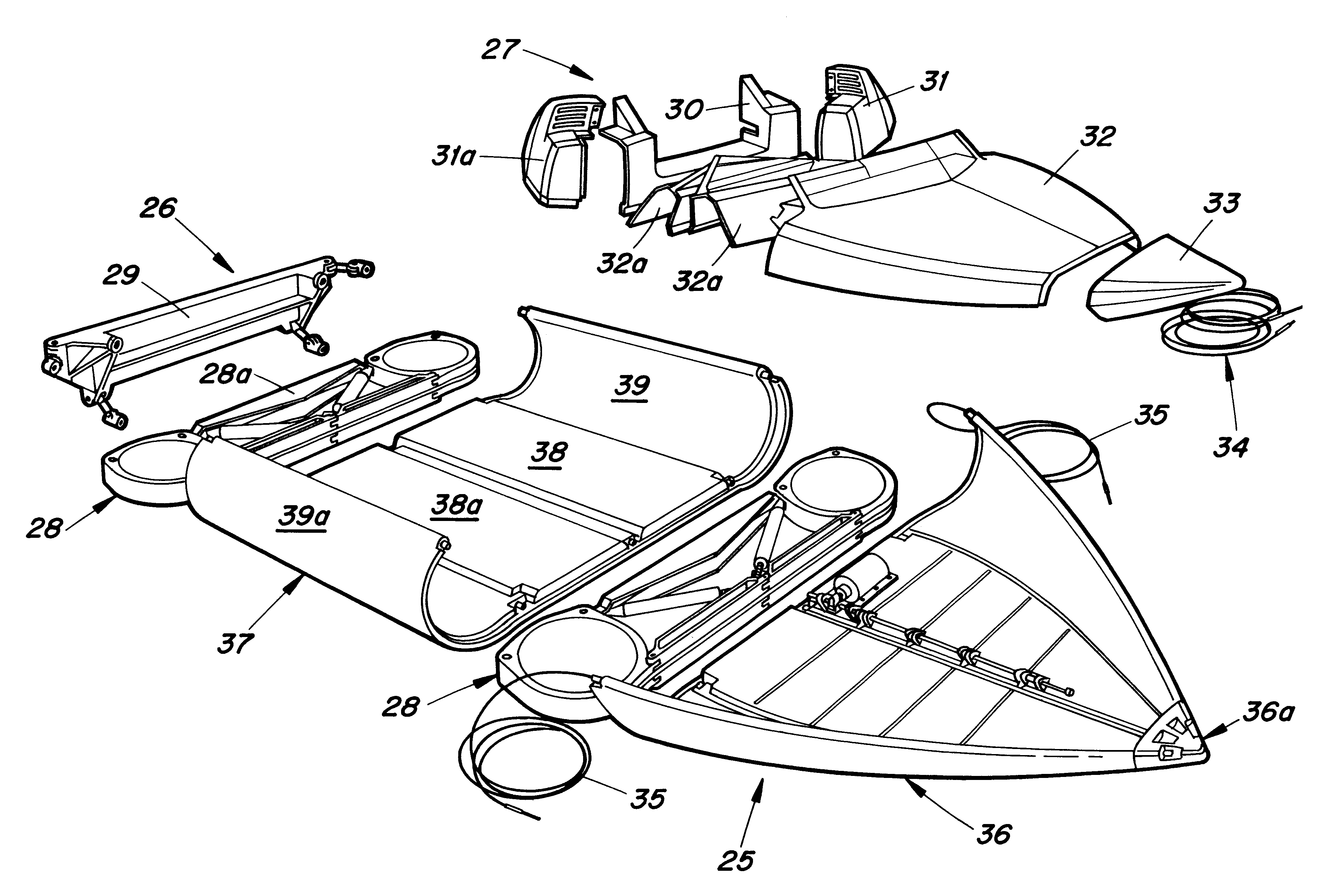
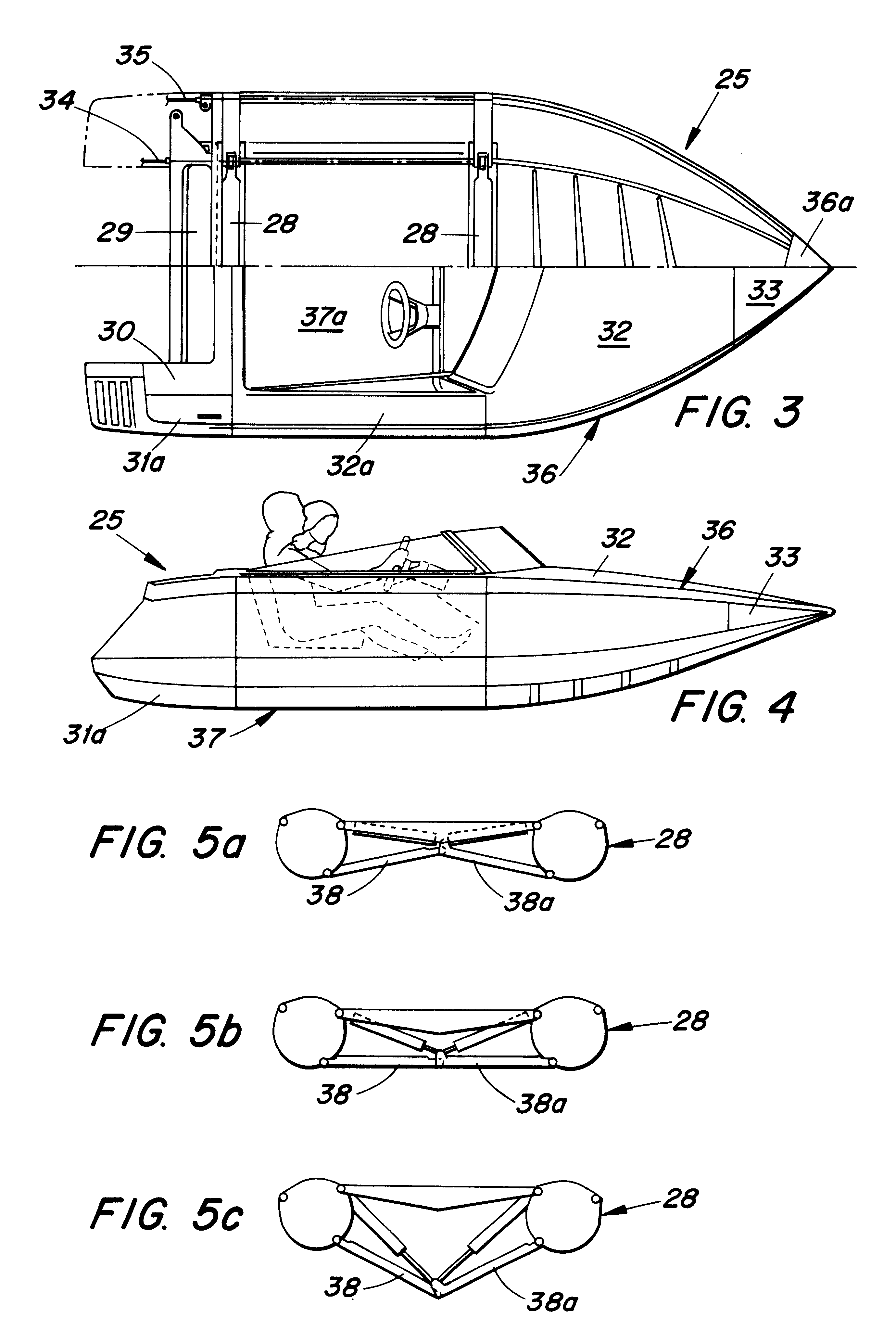
The primary object of the invention is to provide a multi-functional, variable hull water craft that converts to or from a V-shaped hull having a depth of choice, a flat bottom or catamaran, and that has the capacity to make such a conversion in short real time while on the water.
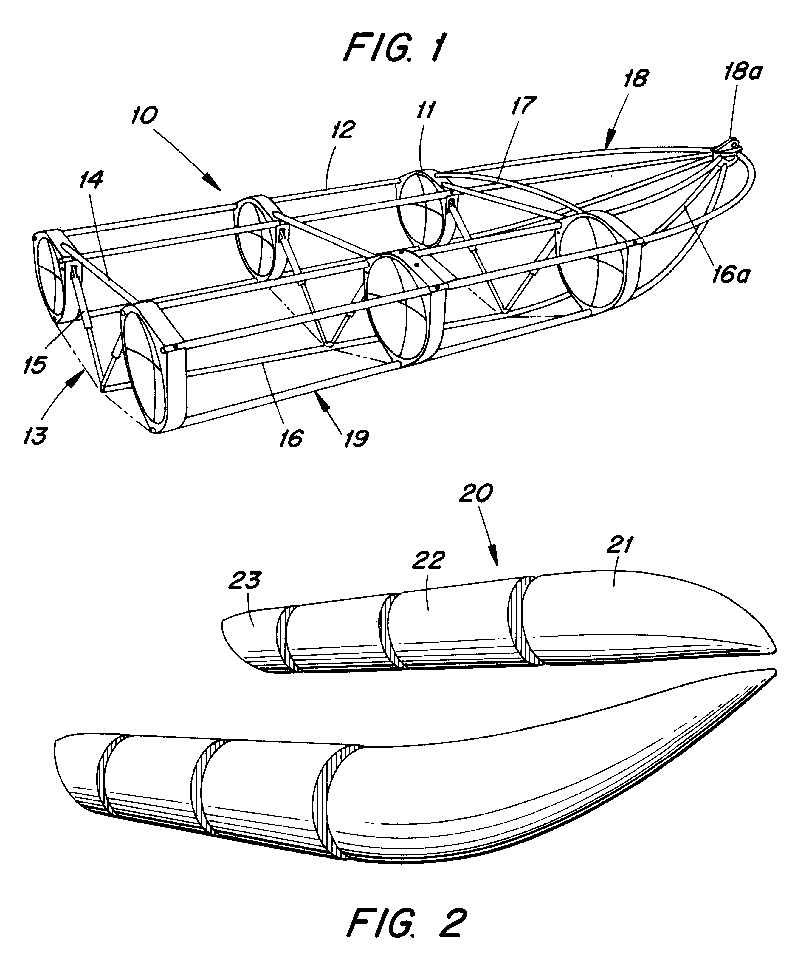
A further object of the invention is to provide a variable hull modular water craft that may be easily upgraded and / or enlarged to virtually any desired length through the use of interlocking sealed modules chat may be added as desired.
In a specific feature of the invention, the bellows means of the boat is effective to dampen shock resulting from waves pounding against the hull portion, and from recurring striking contact with the water because of the up-and-down boat bow movement as it travels along the surface of the water. Energy conversion means located in the boat and responsive to the shock energy induced movement of the bellows means is effective to convert the induced shock absorbing energy obtained by the bellows mechanism into useful compressed air or electrical energy.

Problems solved by technology

Moreover, the prior art does not show how movable parts of a boat structure may be used to capture and convert to useful energy the pounding shock energy sustained from wave action and surface impact as it travels across a water surface.

Method used


Image

  • Marine vessel
  • Marine vessel
  • Marine vessel

Examples


Embodiment Construction

The superstructure of the marine vessel of the invention forms the hull shape, and works on the same principle as an airframe does in an aircraft. The vessel's interconnecting rods and bulkheads fit together to form a complete boat frame to which either an inflatable or rigid skin may be attached. It thus has all the advantages of both the inflatable and rigid hull boats without the possible disadvantages of either one. The structure used in an inflatable hull is the same boat frame used in a rigid hull design. It provides for both the modularity and the variable hull along with another unique aspect for the inflatable version. For if all of the air is removed from every chamber in the vessel, the boat will still function inflation is only needed for maximum performance not flotation. So the vessel overcomes the greatest disadvantage of inflatable boats by eliminating the dangers associated with hull punctures.

In one embodiment, the method for moving the variable hull of the inventi...


PUM


Abstract

A modular marine vessel has a variable hull and a plurality of boat forming modules including a bow section module, a load section module having a bow end and an aft end, and a bulkhead forming module is detachably connected to each bow and aft end of the load section module. The bulkhead forming module that is connected at the bow end of the load section module is detachably connected to the bow section module. Each boat forming and bulkhead forming module includes a topside section and a hull bottom side section. The topside section of each boat forming module has a shell gunnel portion, and the hull bottom side section of each boat forming module has a pivotally mounted bottom shell hull portion. The gunnel and hull portions of the load and bow section modules are detachably connected end-to-end, and sealingly juxtaposed the detachably connected bulkhead forming module to prevent water from entering the boat when the boat engages water. The bottom shell hull portion is pivotally mounted across a keel tunnel using a pneumatic, hydraulic, mechanical, or electro-mechanical actuator to form a preselected hull shape as desired. Novel mechanisms for sealing module connections, for module attachment, for pivoting hull panels, for hull pivot drives, and energy conversion systems for the marine vessel of the invention are disclosed.

Description

This invention relates to recreational boats having variable hull configurations and / or a modular construction system. Particularly, the invention relates to a marine vessel composed of a multiple of modular sections that may be assembled by the consumer who may then convert the hull of the boat as desired to a selected shape to move through water in various conditions, and to enjoy the benefit of varied uses of the water craft.This invention is an improvement on the recreational vessels of U.S. Pat. Nos. 3,846,858 and 3,930,274 comprising convertible assemblies which provide a variety of experiences to the water enthusiast along with enhancing the convenience and safety of the boating public and to those who desire their use on land and ice. All of the advantages of the assemblies of these earlier patents are attendant this invention.Water craft having a system of converting the hull shape into various configurations are known. Such a craft allows its owner to choose any boat hull ...

Claims


Application Information

Patent Timeline
Patent Type & Authority Patents(United States)
IPC IPC(8): B63H19/00B63H19/02B63B7/00B63B39/00B63B1/16B63B1/18B63J3/00B63J3/04B63B7/02B63B17/00B63B1/12B63B1/00B63B1/04
CPCB63B1/04B63B1/22B63B7/06B63B17/0081B63B39/005B63H19/02B63J3/04B63B2001/045B63B2001/145B63B2007/003Y02T70/59Y02T70/5236
Inventor SYFRITT, HAROLD A.
Owner SYFRITT HAROLD A
Learn More