
Variable magnification optical system and optical apparatus having image stabilizing function

a technology of magnification optical system and image stabilizing function, which is applied in the direction of projectors, instruments, printing, etc., can solve the problems of shaking of photographed images in some cases, increasing the frequency of shaking of photographed images, and affecting the quality of photographed images

Inactive Publication Date: 2003-09-09
CANON KK
View PDF20 Cites 36 Cited by
  • Summary
  • Abstract
  • Description
  • Claims
  • Application Information

AI Technical Summary

Problems solved by technology

When shooting is being performed by using a photographic system on a running car, or flying air plane, or the like moving vehicle, the vibrations propagate to the photographic system, thereby causing the shaking of a photographed image in some cases.
Also, when not on the moving vehicle, but when the photographer unstably holds the photographic system by the hand, it often happens that the vibration of the hand causes the shaking of a photographed image.
As the focal length of the photographic system increases to the telephoto region, in particular, the frequency of occurrence of the shaking of a photographed image increases rapidly.
However, this method requires creation of a space in which to move the moving lens unit.
Another problem of this method is that, if an improper one of the lens units is selected to decenter in parallel, the produced amount of decentering aberrations becomes larger.

Method used


Image

  • Variable magnification optical system and optical apparatus having image stabilizing function
  • Variable magnification optical system and optical apparatus having image stabilizing function
  • Variable magnification optical system and optical apparatus having image stabilizing function

Examples


numerical example 2

Aspheric Coefficients:

Numerical Example 3

Aspheric Coefficients:

numerical example 4

Aspheric Coefficients:

TABLE 1

FIGS. 5A1 and 5A2, FIGS. 7A1 and 7A2, FIGS. 9A1 and 9A2 and FIGS. 11A1 and 11A2 are graphic representations of the aberrations of the variable magnification optical systems of the numerical examples 1 to 4, respectively, at image heights of y=0 and y=15 at the wide-angle end for the normal state. FIGS. 5B1 to 5B3, FIGS. 7B1 to 7B3, FIGS. 9B1 to 9B3 and FIGS. 11B1 to 11B3 are graphic representations of the aberrations of the variable magnification optical systems of the numerical examples 1 to 4, respectively, at image heights of y=0 and y=.+-.15 at the wide-angle end during the image stabilizing operation for the tilting of 0.5.degree. of the variable magnification optical system.

FIGS. 6A1 and 6A2, FIGS. 8A1 and 8A2, FIGS. 10A1 and 10A2 and FIGS. 12A1 and 12A2 are graphic representations of the aberrations of the variable magnification optical systems of the numerical examples 1 to 4, respectively, at image heights of y=0 and y=15 at the telephoto end fo...


PUM


Abstract

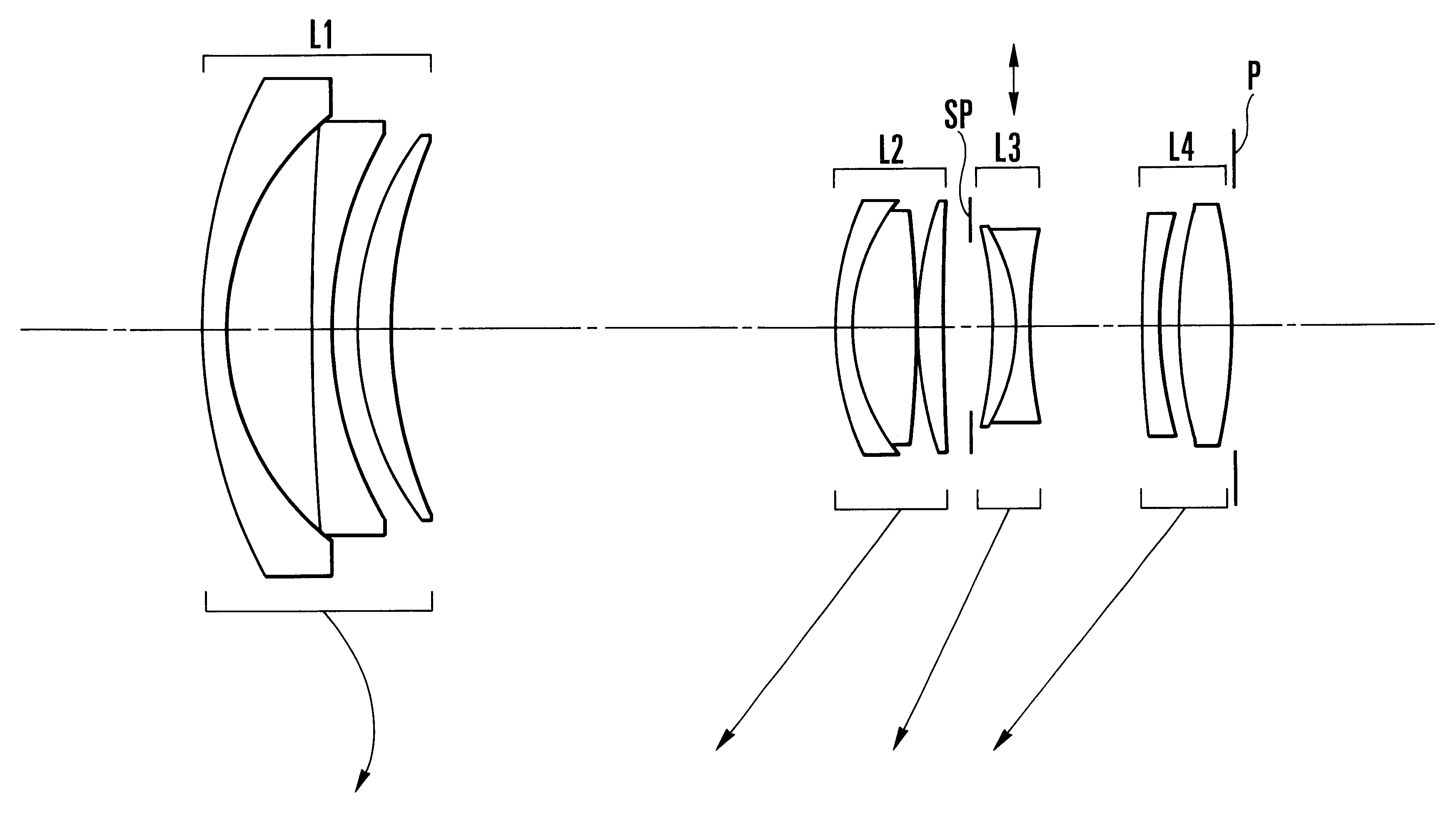
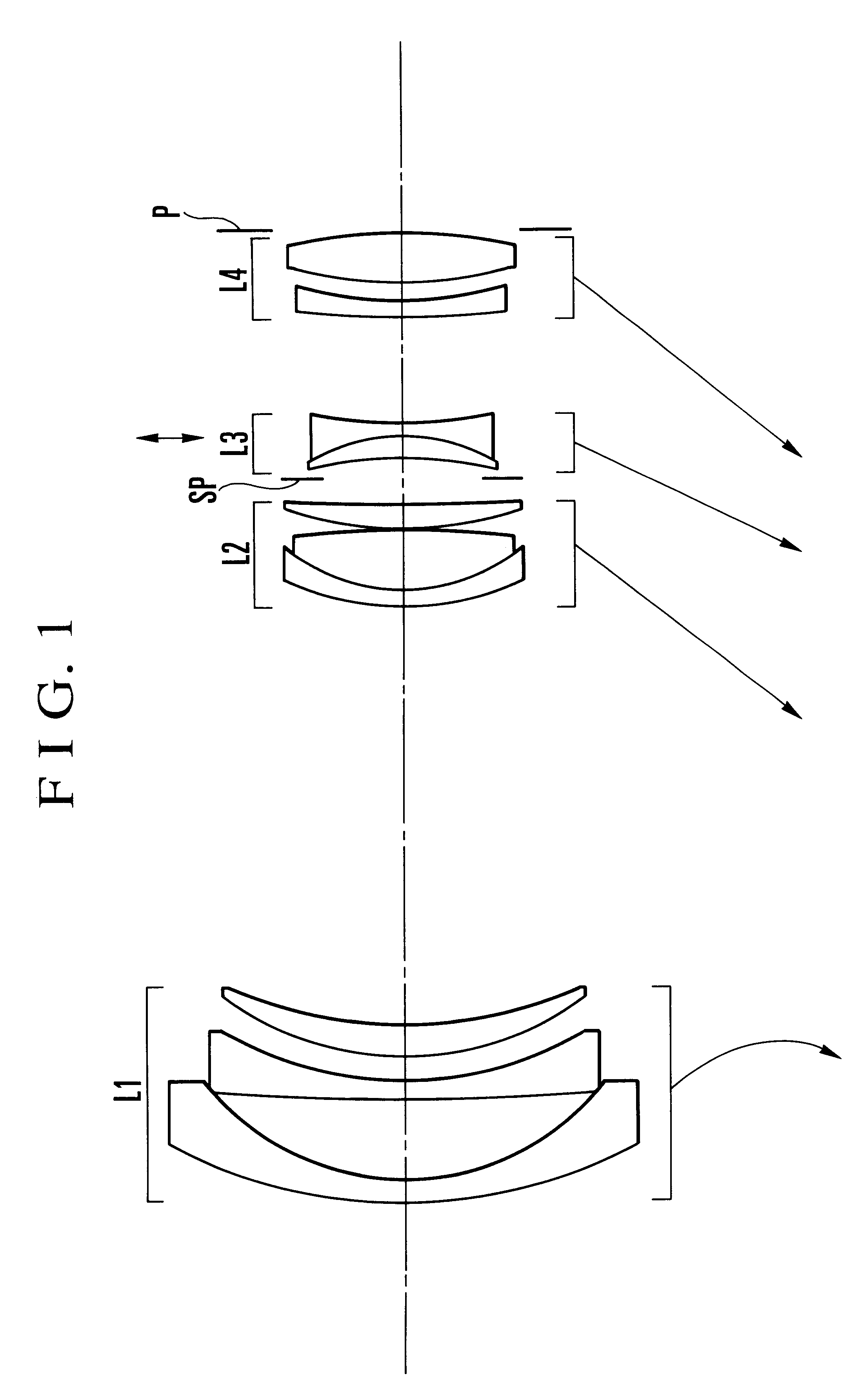
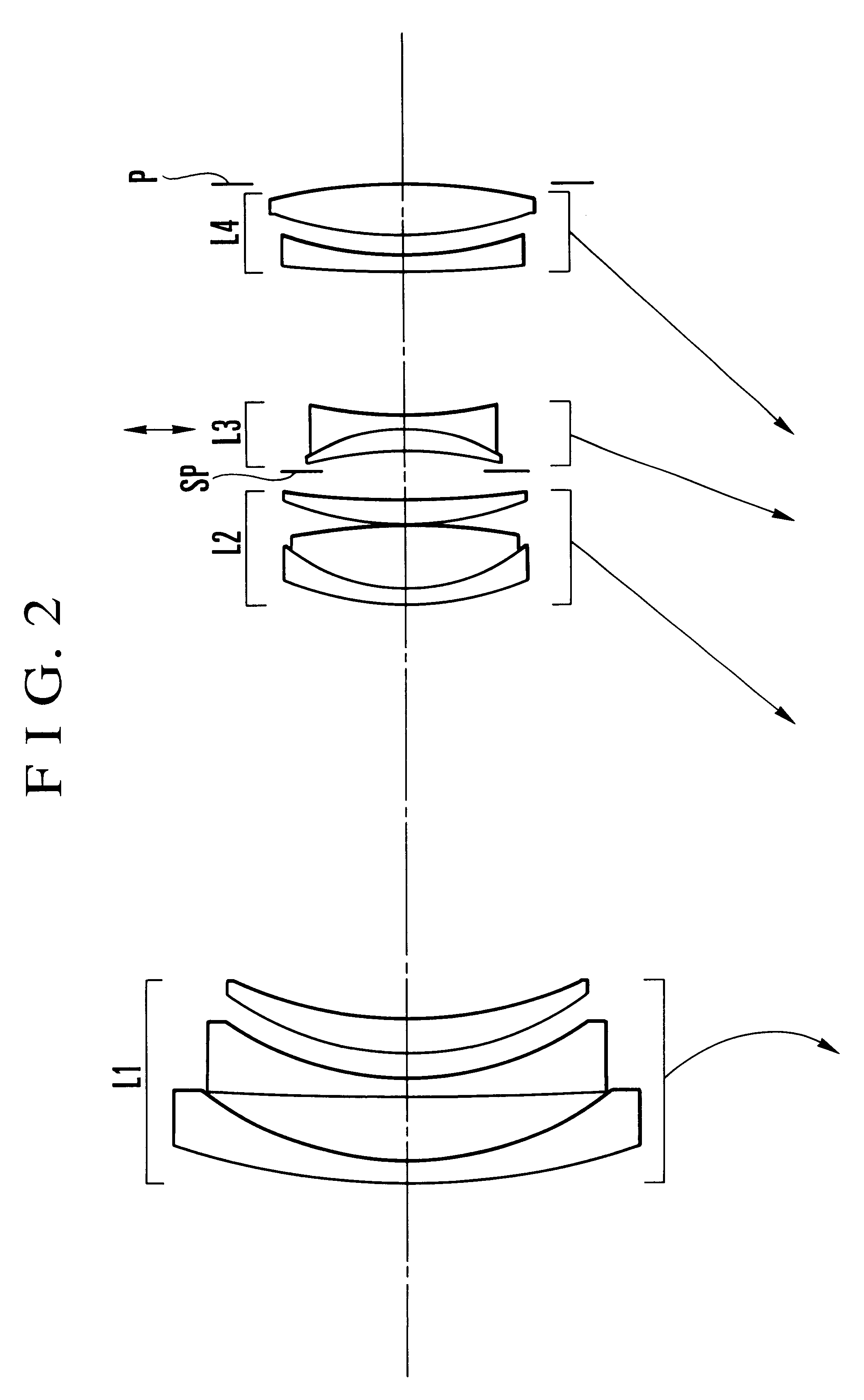
A variable magnification optical system having an image stabilizing function includes, in order from an object side, a first lens unit of negative refractive power, a second lens unit of positive refractive power, a third lens unit of negative refractive power and a fourth lens unit of positive refractive power, wherein the separation between every successive two of the first to fourth lens units is varied to effect variation of magnification, and the third lens unit is so moved as to have directional components perpendicular to an optical axis to compensate for shaking of an image caused by vibration of the variable magnification optical system, the variable magnification optical system satisfying the following conditions:where DiW and DiT are separations between the i-th lens unit and the (i+1)st lens unit at a wide-angle end and at a telephoto end, respectively, and fi is a focal length of the i-th lens unit.

Description

1. Field of the InventionThe present invention relates to variable magnification optical systems and, more particularly, to a variable magnification optical system having an image stabilizing function in which one lens unit, constituting a part of the variable magnification optical system, is so moved as to have directional components perpendicular to an optical axis to optically compensate for the shaking of a photographed image caused by the vibration (tilting) of the variable magnification optical system, thereby obtaining a stabilized image, and which optical system is suited to photographic cameras, electronic cameras, video cameras or the like.2. Description of Related ArtWhen shooting is being performed by using a photographic system on a running car, or flying air plane, or the like moving vehicle, the vibrations propagate to the photographic system, thereby causing the shaking of a photographed image in some cases. Also, when not on the moving vehicle, but when the photogra...

Claims


Application Information

Patent Timeline
IPC IPC(8): G02B26/02G02B13/18G02B15/177G02B15/20G03B5/00
CPCG02B15/177G02B27/646G02B15/144511
Inventor ENDO, HIROSHI
Owner CANON KK
Learn More