
Method for examining rotationally symmetrical objects

Inactive Publication Date: 2003-08-05
BASLER AG
View PDF16 Cites 10 Cited by
  • Summary
  • Abstract
  • Description
  • Claims
  • Application Information

AI Technical Summary

Benefits of technology

According to the invention, this objective is attained due to the fact that preferably each object contains at least one marking or is provided with at least one marking. The marking makes it possible to unequivocally determine the angular position of each object about the rotational axis with reference to the marking for objects manufactured in the same manufacturing process. At least one section of each of the objects is scanned by at least one scanning element and the marking is detected during the examination process. The scanning result and / or examination result of the geometric regions with corresponding positions on the objects relative to the marking is determined and / or evaluated and / or displayed on a display element in the same angular position relative to the marking. The evaluation means evaluating the defects of the respective objects have the same or at least approximately the same position relative to the angular position of the marking and the same radial distance from the rotational axis with other criteria than stochastically occurring defects. Consequently, a defect that always occurs at the same position will always have the same geometric data up to the examination station independent of the rotation of the object to be examined. It is quite obvious that this makes it possible to recognize and classify possible system defects, in particular, defects in the stamper. The determination, evaluation and / or illustration of an otherwise rotationally symmetrical object which is based on the rotating direction makes it possible to rapidly and reliably classify such continuously occurring defects as stamper defects. The defect classification, namely the question whether such a defect results in refuse or not, can be correspondingly optimized.
It is quite apparent that the method according to the invention makes it possible to easily detect possible system defects. It is also possible, in particular, during the manufacture of pressed objects, to detect defects in the stampers because such a defect always leads to the same defect at the same position. Without a marking and its detection, it would not be possible to measure and illustrate the object to be examined always in the same angular position so as to evaluate identical defects in the same fashion and / or with identical coordinates or corresponding data. Due to the invention, an evaluation and an illustration can always be achieved in the same angular position referring to a starting position. Consequently, the result of the examination can be more confidently accepted. The invention, in particular, also makes it possible to detect defects in the stampers which would not result in refuse in individual instances during the manufacture of optical data carriers. In this case, the sensitivity of the examination method can be increased if such defects always occur at the same position, i.e., the production process can be manipulated in a timely fashion.

Problems solved by technology

However, this has the disadvantage that, in particular, defects which are produced during essential manufacturing steps and always occur at the same position are not always recognized as such, namely because these defects occur at the same radial distance from the rotational axis, but in different angular positions due to the undefinable rotation, to which the object to be examined is subjected before it reaches the examination station.
A defect in the stamper may cause the entire production to result in refuse.

Method used


Image

  • Method for examining rotationally symmetrical objects
  • Method for examining rotationally symmetrical objects

Examples


Embodiment Construction

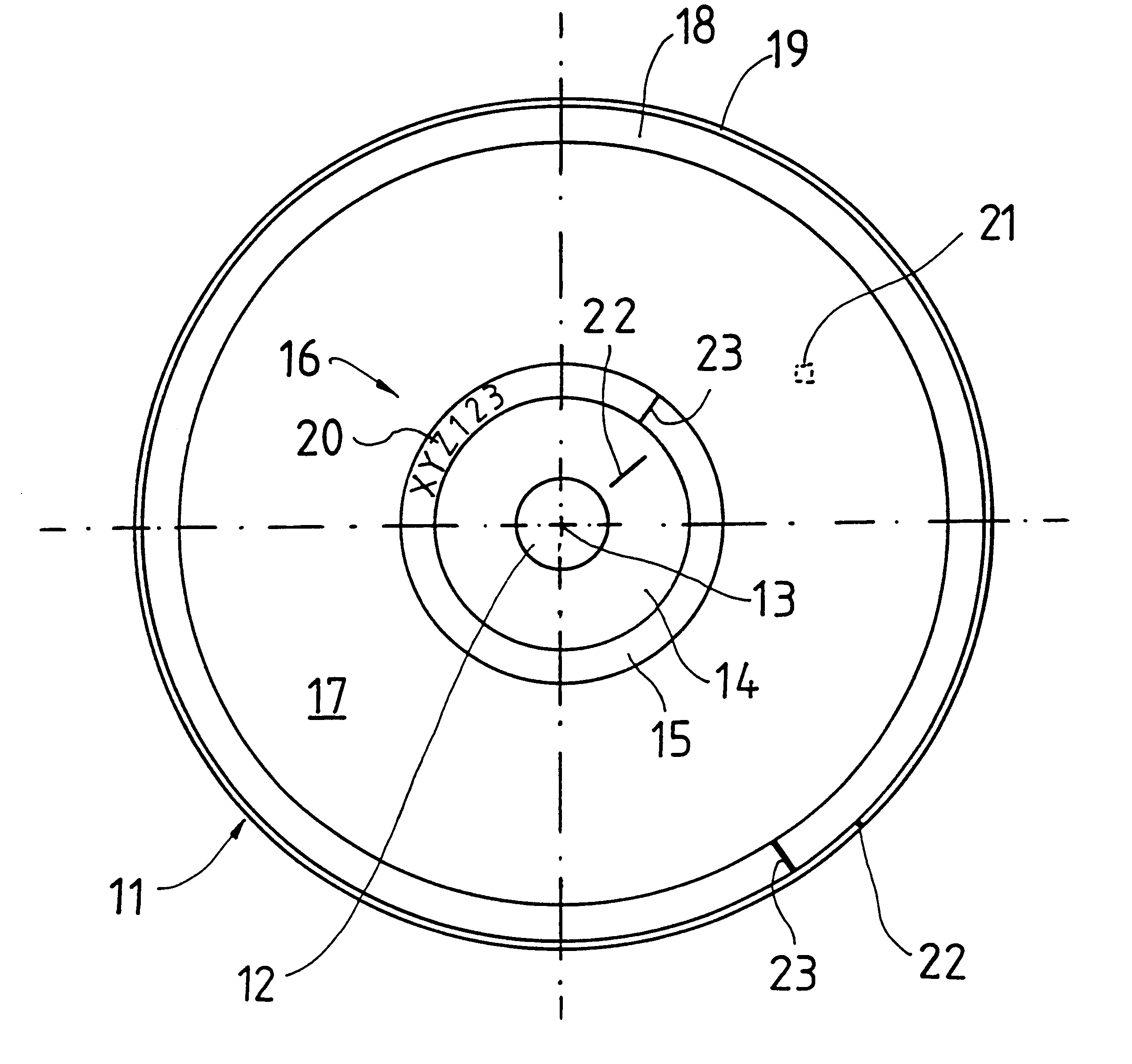
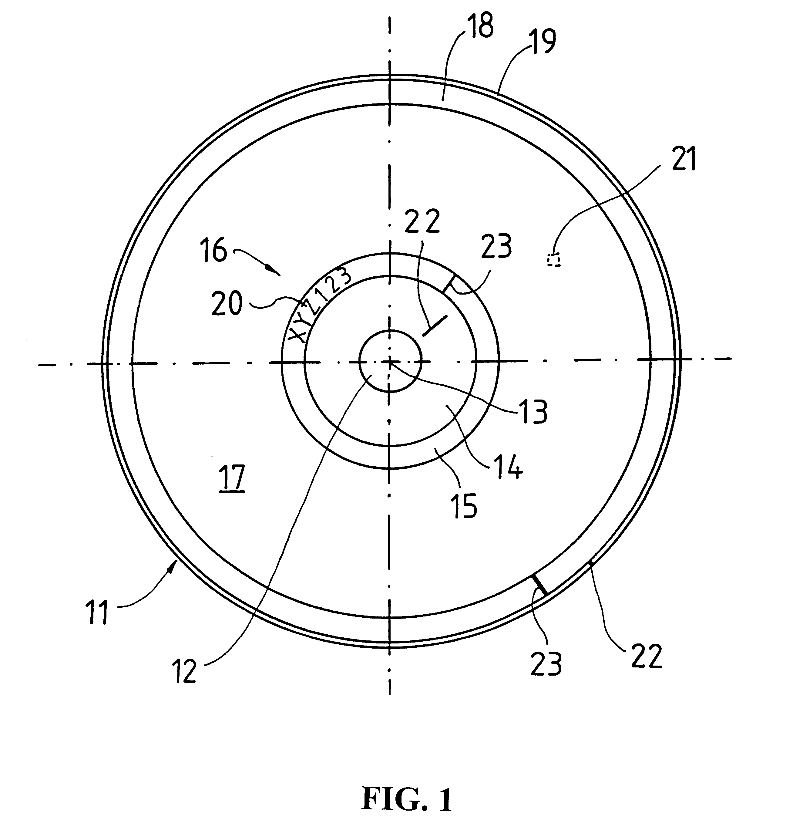
The Compact Disk (CD) 11 shown in the figure is conventionally realized in the form of a circular disk with a central hole 12. This means that the CD is entirely symmetrical in reference to the rotational axis 13. The central hole 12 is usually bordered by an inner coaxial edge region 14 for holding the CD in the corresponding player. A coaxial region 15 that contains the identification code, namely the ID code 16, is situated adjacent to the aforementioned edge region. This coaxial region 15 is surrounded by the data area 17. Depending on the data quantity, a lead-out 18 or the outer edge region 19 is situated adjacent to the data area.

It is quite apparent that such a CD, in particular, the data area 17, always appears identical to an optical scanning element of an examination device independently of the rotation if no additional measures are provided. This is the reason why defects which, for example, always occur at the same position referred to the radial distance and the angula...


PUM


Abstract

The invention pertains to a method for examining a series of objects that are symmetrical in reference to a rotational axis, e.g., circular disks, during or after the manufacturing process of the disks. In particular, the invention pertains to the optical examination of circular data carriers, e.g., CD, DVDs, CD-Rs or the like. The invention proposes that each object contains at least one marking or is provided with at least one marking. The marking makes it possible to unequivocally determine the angular position of each object about the rotational axis in reference to the marking for objects manufactured in the same manufacturing process. At least one section of the objects is scanned by at least one scanning element, and the marking is detected during the examination process. The scanning result and / or examination result of geometric regions with corresponding positions on the objects in reference to the marking is determined and / or evaluated and / or displayed on a display element in the same angular position in reference to the marking. A defect that always occurs at the same position will always have the same geometric data independent of the rotation of the object to be examined during its transport to the examination point and can be treated with other criteria.

Description

The invention pertains to a method for examining a series of objects that are symmetrical in reference to a rotational axis, e.g., circular disks. The invention pertains, in particular, to the optical examination of circular data carriers, e.g., CDs, DVDs, CD-Rs and the like. Although the following description primarily pertains to one of these data carriers, the invention is not limited to objects of this type.It is known to carry out a 100% examination of optical data carriers during or after the manufacturing process of the optical data carriers. When examining CDs, CD-Rs or DVDs, optical methods are utilized in which the objects to be examined are turned about their rotational axis and scanned. The surface to be examined, e.g., the flat side having a data area, is scanned and examined with respect to possible defects. Methods of this type are, for example, known from DE 44 34 473 A1, DE 44 34 474 A1 and DE 44 34 475 A1. WO 97 / 20312 describes a method in which a circular object i...

Claims


Application Information

Patent Timeline
IPC IPC(8): G01N21/95G01N21/88G11B7/26
CPCG01N21/9506G11B7/26
Inventor KAUPP, ANSGAR
Owner BASLER AG
Learn More