Supercharge Your Innovation With Domain-Expert AI Agents!

Method and apparatus for implementing microprocessor control logic using dynamic programmable logic arrays

a microprocessor and dynamic logic technology, applied in the field of microprocessors, can solve the problems of large-scale integrated circuit design that can become very complex with respect to timing, microprocessors are demanding increased processing power, and need for increased circuit density

Inactive Publication Date: 2003-07-29
GOOGLE LLC
View PDF29 Cites 11 Cited by
  • Summary
  • Abstract
  • Description
  • Claims
  • Application Information

AI Technical Summary

Problems solved by technology

The market for microprocessors is demanding increased processing power, which can be achieved through increased clock frequencies and complexity (for example parallel operation capacity).
Increased complexity creates the need for increased circuit density, and use of architectures requiring fewer devices to implement the microprocessor circuits.
Although these circuits are very efficient from a device per gate standpoint, due to the dynamic nature of the logic (logic signals exist as pulses propagating through a logical network, rather than static stages), design of large scale integrated circuits can become very complex with respect to timing.
As clock frequencies increase, timing problems increase, particularly with respect to the interconnection of various functional sub-systems that are displaced from each other within a monolithic circuit.
ROM is not the most efficient way to implement control logic, as a separate row of hard-wired values is required for each combination of input address lines.
The difficulty in this approach is that the synthesis of the logic will yield timing variations.
These logic variations can be cured by insertion of delays, but this may not provide the most optimum performance.
Part of the complexity of timing design is created by increased microprocessor die area.
Propagation delays from various parts of the microprocessor have increased, making it difficult to align data flow and control information so that data manipulation and next state sequencing can proceed properly.
This is generally the upper limit on clock frequency for a given processor design.
A second part of timing constraints is device skew.

Method used


Image

  • Method and apparatus for implementing microprocessor control logic using dynamic programmable logic arrays
  • Method and apparatus for implementing microprocessor control logic using dynamic programmable logic arrays
  • Method and apparatus for implementing microprocessor control logic using dynamic programmable logic arrays

Examples


Embodiment Construction

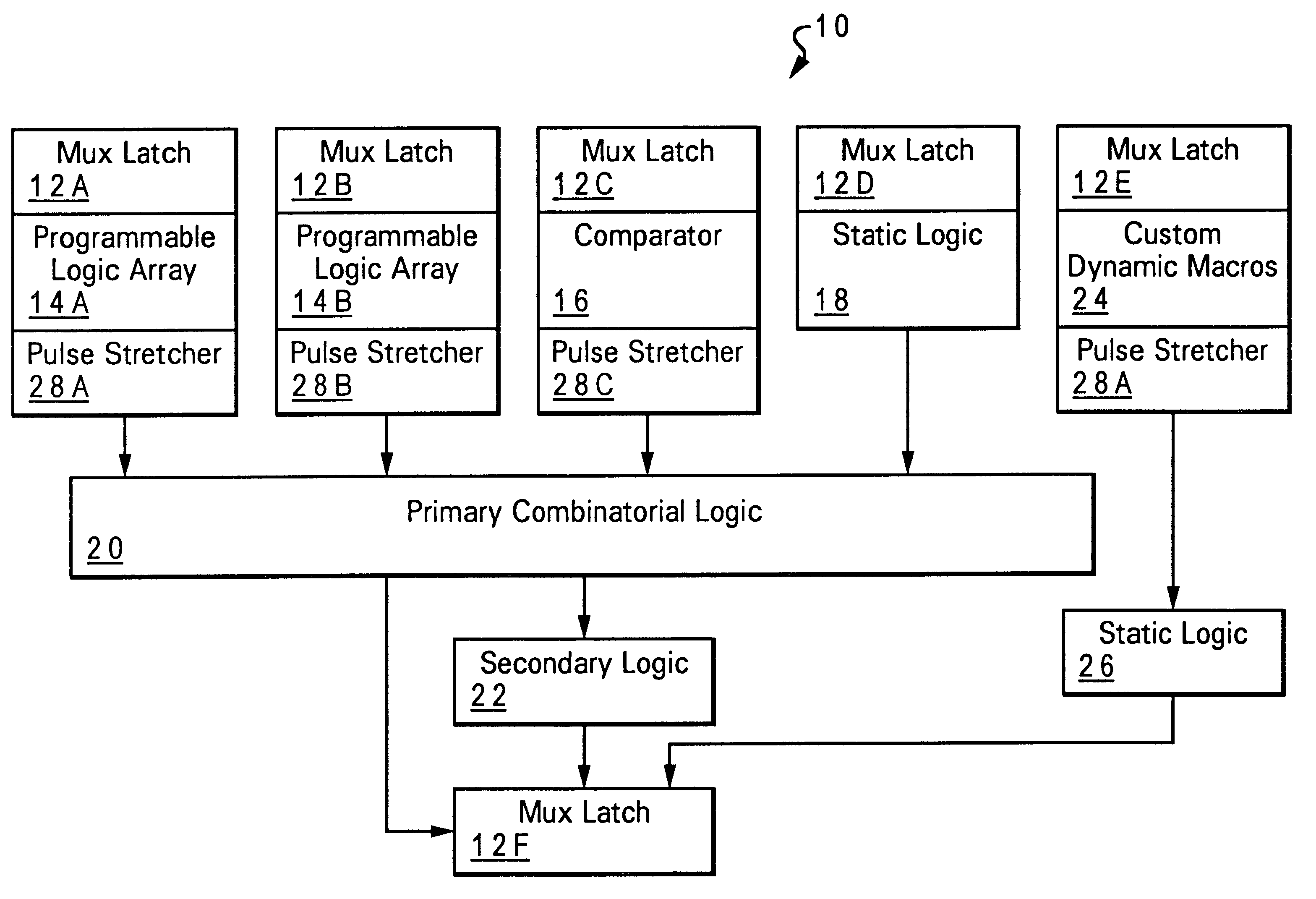
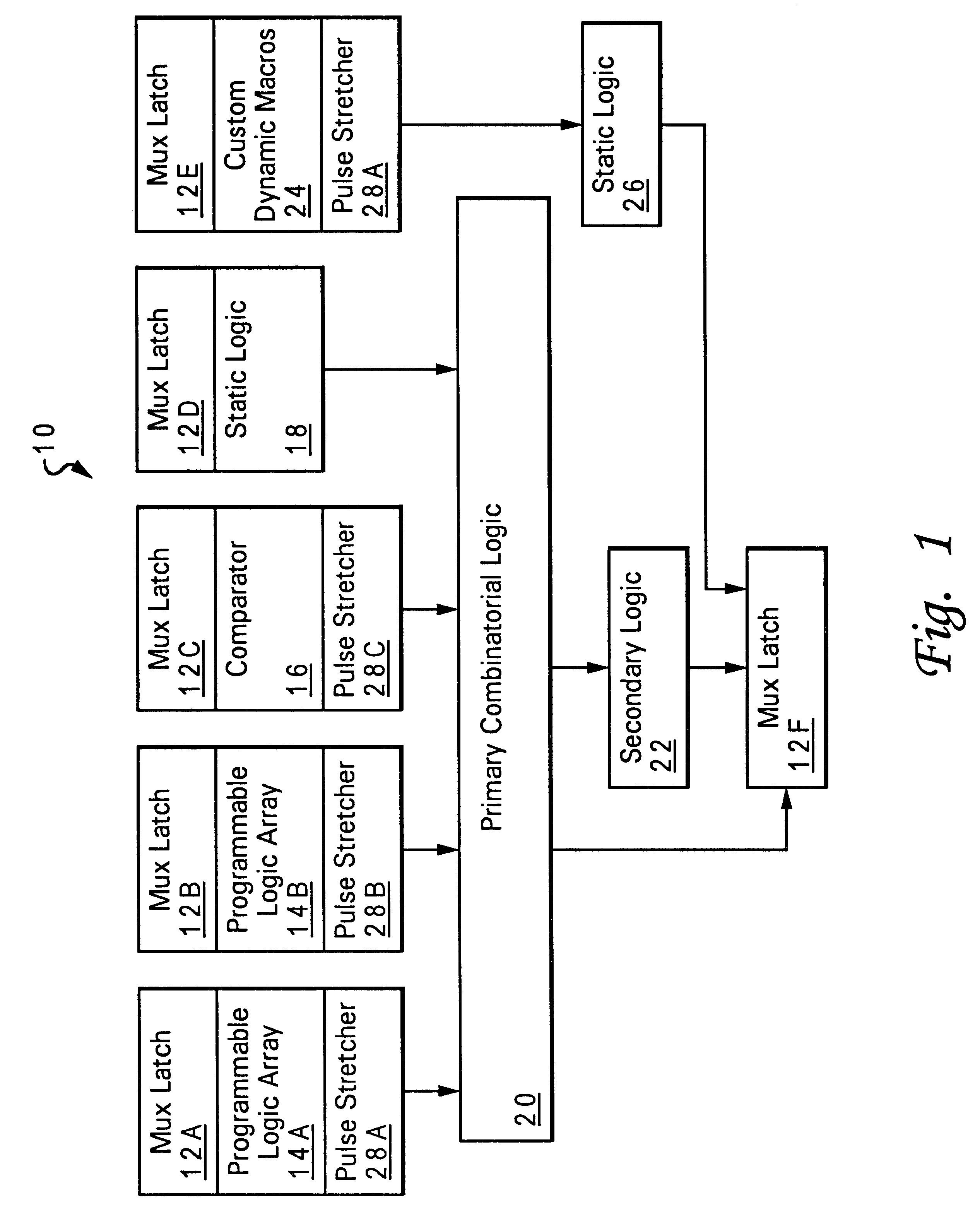
The use of a dynamic programmable logic array (PLA) to entirely implement control logic in a microprocessor has been limited in the past. Timing skew of PLA inputs, combined with a logic depth of at least three gates (an input plane, an output plane and an intermediate strobed stage to stabilize the logical result), have restricted the use of PLAs in high speed microprocessors.

Using the balancing techniques disclosed in BALANCED-DELAY PROGRAMMABLE LOGIC ARRAY AND METHOD FOR BALANCING PROGRAMMABLE LOGIC ARRAY DELAYS, incorporated by reference above, along with the partitioning techniques disclosed in "METHOD AND APPARATUS FOR REDUCING DYNAMIC PROGRAMMABLE LOGIC ARRAY PROPAGATION DELAY", also incorporated by reference above, provide a faster PLA that is suitable for use in the primary control logic path of the microprocessor. In addition, the incorporation of pulse stretching circuits on the outputs of the PLA make it possible for the PLA to combine inputs that have wiring delays due ...


PUM


Abstract

A method and apparatus for using dynamic programmable logic arrays in microprocessor control logic provide decreased power and increased clock frequencies for data processing systems, by using programmable logic arrays exclusively for the control logic. The method and apparatus further simplify the design of the control logic and closure of timing within the microprocessor, by providing overlap of control logic evaluations and data transfers within the microprocessor.

Description

1. Field of the InventionThe present invention generally relates to microprocessors, and more particularly to a microprocessor implemented with dynamic logic wherein control logic is implemented in dynamic programmable logic arrays.2. Description of Related ArtThe market for microprocessors is demanding increased processing power, which can be achieved through increased clock frequencies and complexity (for example parallel operation capacity). Increased complexity creates the need for increased circuit density, and use of architectures requiring fewer devices to implement the microprocessor circuits.One technology that has been applied in recent years to an increasing number of microprocessor and other integrated circuits, is dynamic logic, sometimes referred to as "Domino Logic Circuits". Although these circuits are very efficient from a device per gate standpoint, due to the dynamic nature of the logic (logic signals exist as pulses propagating through a logical network, rather t...

Claims


Application Information

Patent Timeline
Patent Type & Authority Patents(United States)
IPC IPC(8): H03K5/06H03K17/693H03K5/04
CPCH03K5/06H03K17/693
Inventor COULMAN, PAULA KRISTINEDHONG, SANG HOOFLACHS, BRIAN KINGHOFSTEE, HARM PETERPARK, JAEHONGPOSLUSZNY, STEPHEN DOUGLASSILBERMAN, JOEL ABRAHAMTAKAHASHI, OSAMU
Owner GOOGLE LLC
Features
  • R&D
  • Intellectual Property
  • Life Sciences
  • Materials
  • Tech Scout
  • Unparalleled Data Quality
  • Higher Quality Content
  • 60% Fewer Hallucinations
Learn More