
Power supply for electric arc welding

a technology of power supply and electric arc welding, which is applied in the direction of welding apparatus, ac-ac conversion, manufacturing tools, etc., can solve the problems of high weight and achieve the effects of low cost, substantial engineering and lead time, and high weigh

Inactive Publication Date: 2003-07-29
LINCOLN GLOBAL INC
View PDF7 Cites 23 Cited by
  • Summary
  • Abstract
  • Description
  • Claims
  • Application Information

AI Technical Summary

Benefits of technology

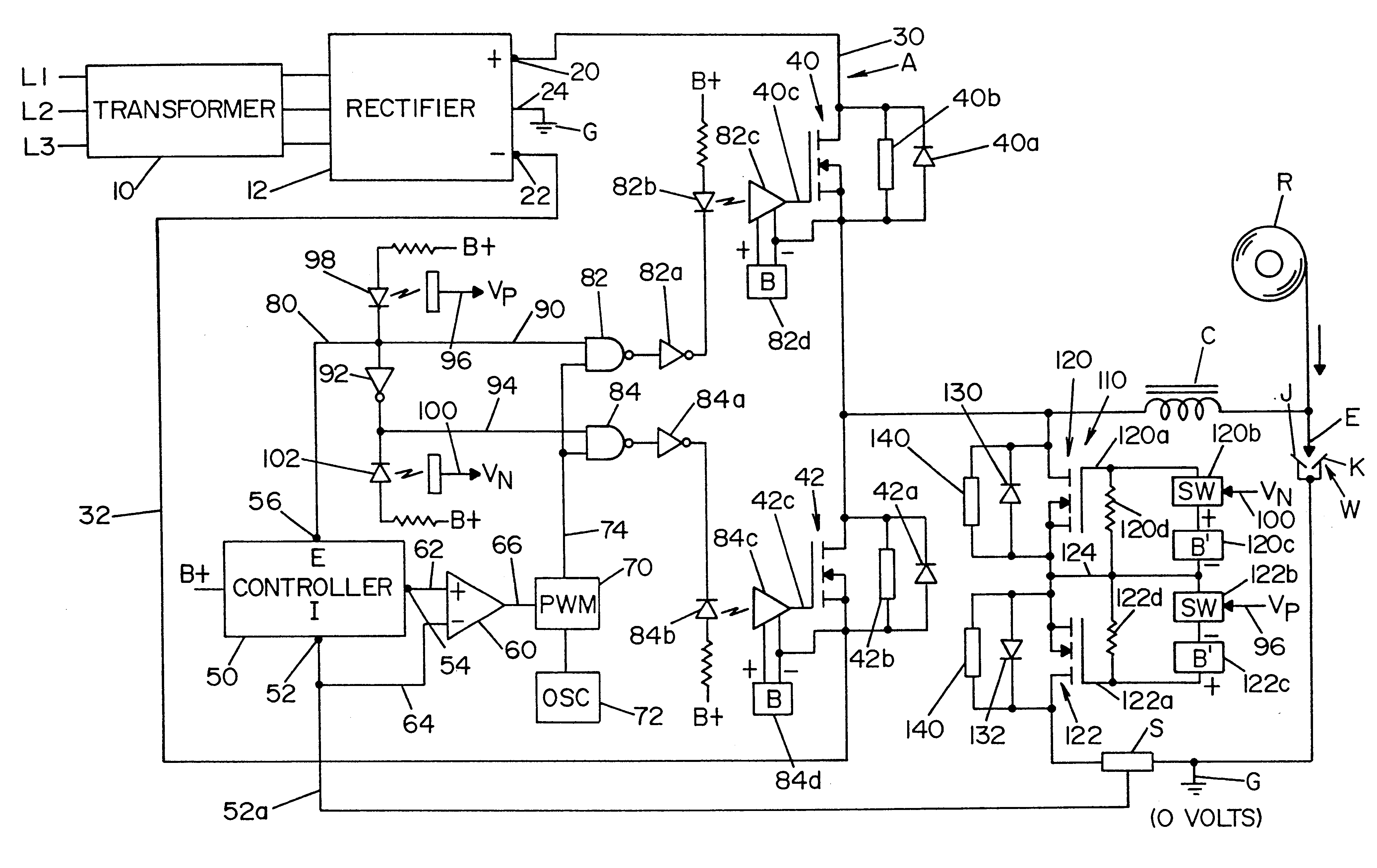
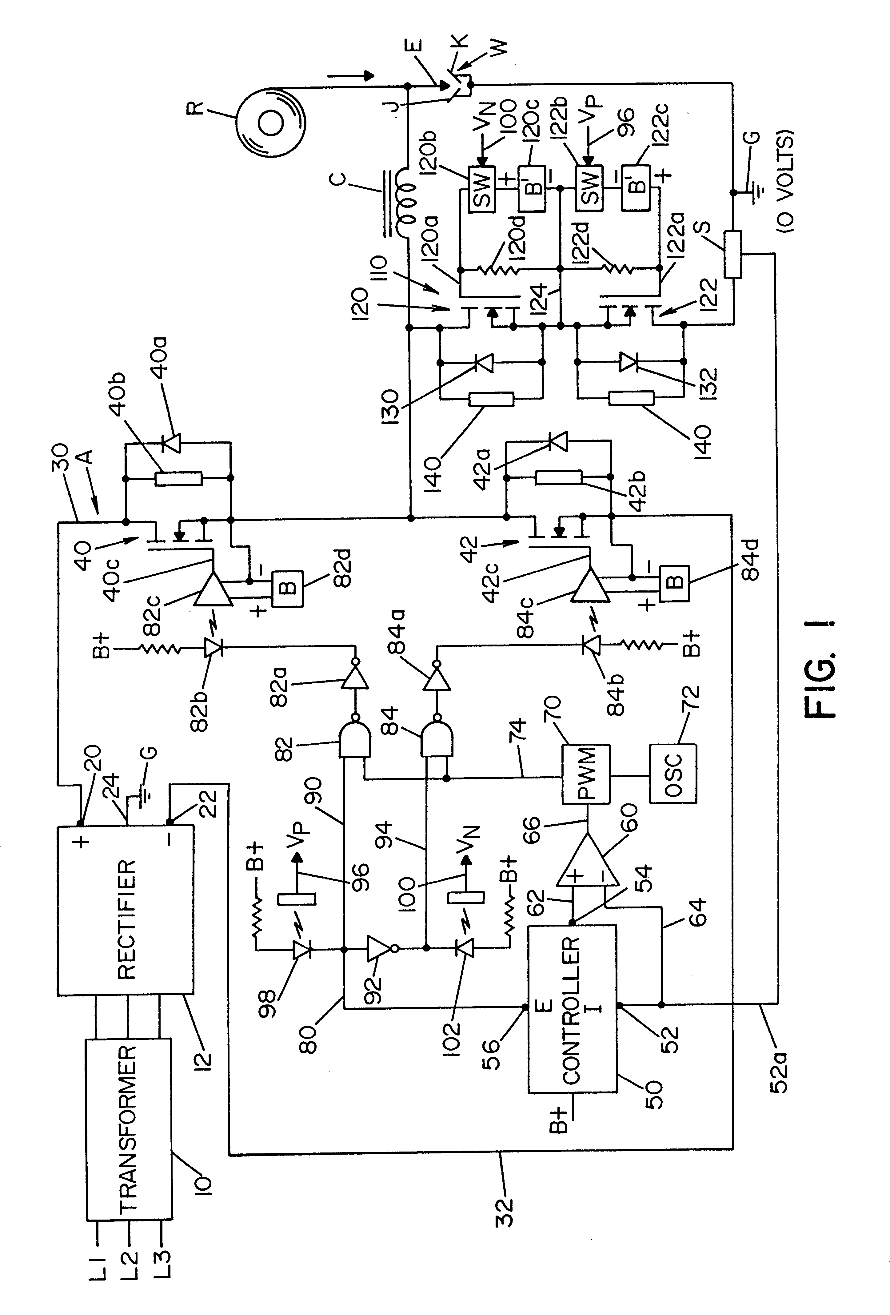
The present invention relates to an improved power supply for high current, AC electric arc welding, which power supply can be used in the field for pipe welding and other high current applications. A transformer converts AC line voltage, such as single phase or three phase line voltage, to a low output AC voltage, such as 70-100 volts. The output voltage is rectified and drives two standard down chopper modules, each driven by a common pulse width modulator. In some instances, each module may be driven by a dedicated pulse width modulator. A somewhat standard control board with a microprocessor controller sets the pulse width and, therefore, the magnitudes of the positive and negative current pulses constituting the AC welding current. This relatively inexpensive power supply can replace large inverter units without substantial engineering and lead time. The only disadvantage of the present invention is its high weight, due to the large input transformer; however, such weight is not a serious problem in pipe welding or other high current applications. By using the present invention, the power supply is robust and simple to construct. The power supply is constructed with readily available components.
Still a further object of the present invention is the provision of a power supply, as defined above, which power supply obtains the advantage of parallel mounted inverters, or large high cost inverters without the expense and complexity or such paralled (word?) inverters.
Yet another object of the present invention is the provision of a power supply, as defined above, which power supply provides the simplicity of a down chopper while obtaining an AC welding current.

Problems solved by technology

The only disadvantage of the present invention is its high weight, due to the large input transformer; however, such weight is not a serious problem in pipe welding or other high current applications.

Method used


Image

  • Power supply for electric arc welding
  • Power supply for electric arc welding
  • Power supply for electric arc welding

Examples


Embodiment Construction

Referring now to the drawings wherein the showings are for the purpose of illustrating preferred embodiments of the invention only, and not for the purpose of limiting same, FIG. 1 shows a high frequency inverter power supply A for developing an output AC welding current of at least 1,000-2,000 amperes across the welding gap between electrode E and workpiece W which, in practice, is the joint between two adjacent pipe sections J,K. In accordance with standard practice, inductor C having an inductive impedance which smooths out the current flow through the welding operation defined by electrode E and workpiece W. Electrode E is an advancing wire from supply reel R which is melted by the arc created by the AC welding current. Workpiece W, comprising pipe sections J,K, is connected to system ground G. This ground is a zero voltage rail or bus to define the positive and negative current portions. The AC current in the welding operation is detected or sensed through a shunt S to create a...


PUM

PropertyMeasurementUnit
frequencyaaaaaaaaaa
arc currentaaaaaaaaaa
output voltageaaaaaaaaaa

Abstract

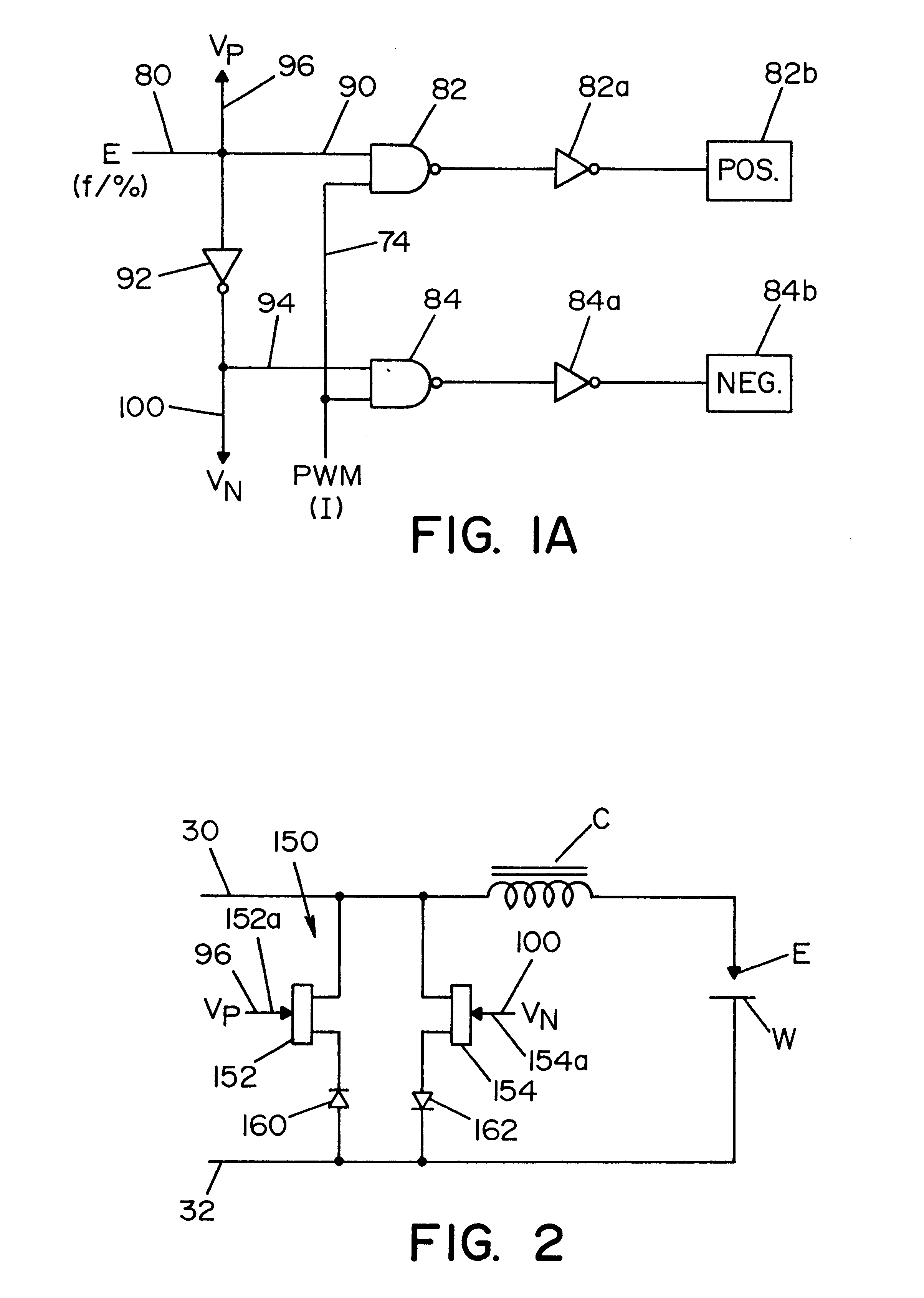
A power supply connectable to a source of AC line voltage for AC electric arc welding by an AC arc current across a welding gap between an electrode and a workpiece, the power supply comprises a high capacity transformer that converts said line voltage to an AC output voltage, and a rectifier that converts the AC output voltage to a DC voltage between a positive terminal and a common terminal at generally zero volts and a negative terminal and the common terminal. The power supply has a first switch that connects the positive terminal to the common terminal across the gap when a gate signal is applied to the first switch, a second switch for connecting the negative terminal to the common terminal across the gap when a gate signal is applied to the second switch and a pulse width modulator operated for generating pulses at a frequency of at least about 18 kHz. A logic network has a first circuit for directing the pulses to the first switch for a first time, a second circuit for directing the pulses to the second switch for a second time and a controller to alternately operate first and second circuits to create AC arc welding current.

Description

The present invention relates to the art of electric arc welding and more particularly to a power supply for electric arc welding with an AC arc current.INCORPORATION BY REFERENCEThe power supply constructed in accordance with the present invention is used to create a positive and negative current pulses having high magnitude generally exceeding 1,000 amperes. The individual pulses are created by a pulse width modulator operating switches in accordance with standard practice. Since the switches must change polarity at high voltages, the power supply is constructed to cause switching from one polarity to the next opposite polarity at reduced current levels. The technique is disclosed in prior application Ser. No. 233,235 filed Jan. 19, 1999 for a different type of current pulse. This prior application is incorporated by reference herein for the purposes of showing a technique for switching a polarity of currents at reduced levels in a high current arc welder. A technique for providin...

Claims


Application Information

Patent Timeline
Patent Type & Authority Patents(United States)
IPC IPC(8): B23K9/10B23K9/073B23K9/09H02M5/458H02M9/00
CPCB23K9/1062B23K9/1075
Inventor STAVA, ELLIOTT K.
Owner LINCOLN GLOBAL INC
Learn More