
Method and device for providing a layer to a piston ring

Inactive Publication Date: 2003-07-29
KONCENTRA MARINE & POWER
View PDF12 Cites 7 Cited by
  • Summary
  • Abstract
  • Description
  • Claims
  • Application Information

AI Technical Summary

Benefits of technology

The energy beam is allowed to act on the coating powder, its energy being absorbed by the powder and converted into heat, which melts the powder. By using correctly chosen energy radiation, the powder is melted with a minimum effect on the piston ring blank. This melting is just enough for satisfactory welding of the coating layer and thus allows a minimisation of the Heat Affected Zone (HAZ) in the piston ring blank. This finally results in a piston ring having a strong coating layer which is firmly bound to the piston ring.
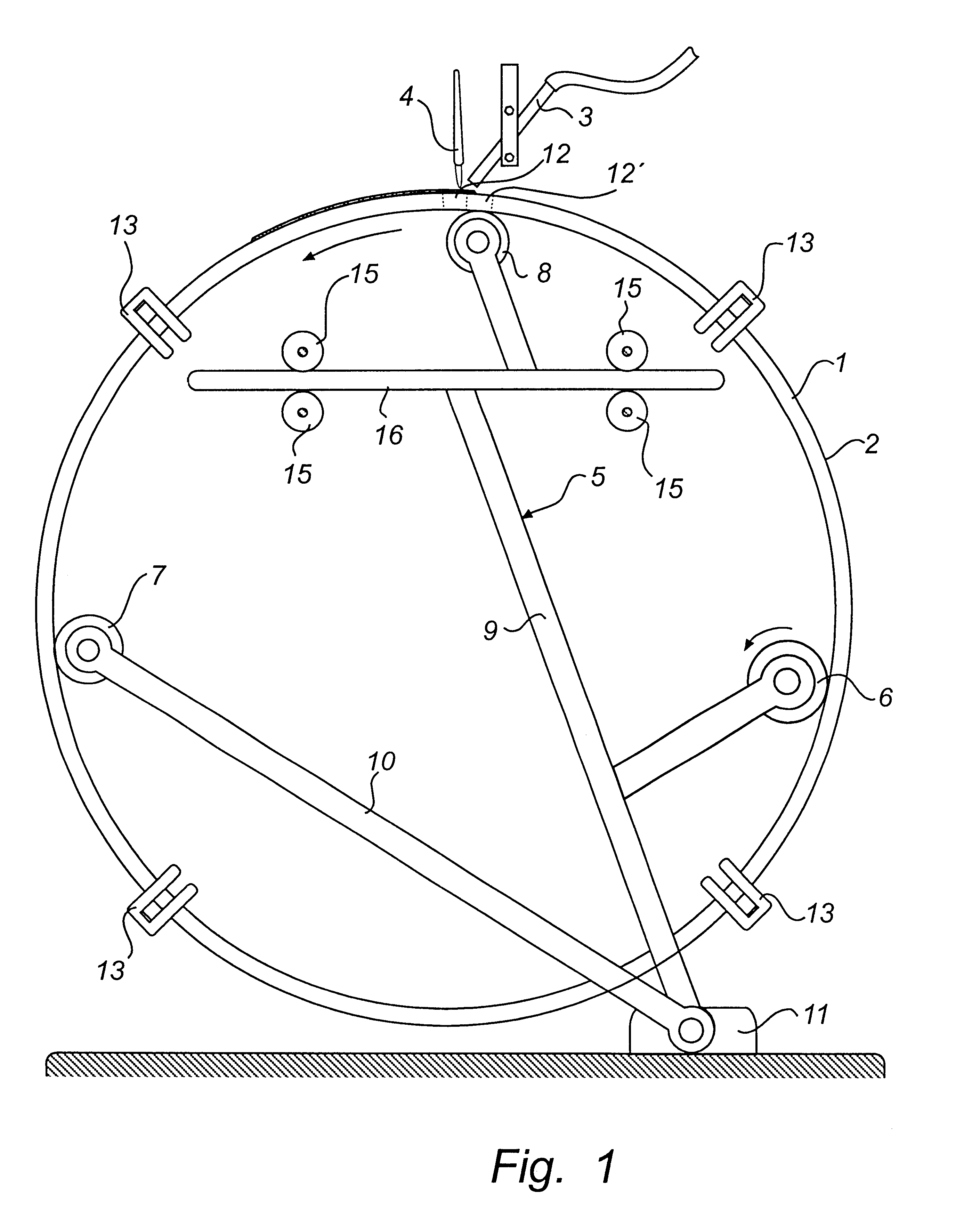
Advantageously, the suspension device can be a device in which the piston ring is caused to rotate. When the piston ring blank is somewhat oval, it is particularly suitable to use a device comprising spring-loaded supporting means, which act radially outwards to the inside of the piston ring blank. Owing to this, the supporting means follows the oval shape without any difficulties. The supporting means and the heating elements can easily be arranged at the circumference of the piston ring blank without interfering with each other, for instance, in a manner such as described in the embodiment below.

Problems solved by technology

A high degree of wear, heat and corrosive attack cause the piston rings to quickly wear, thus necessitating replacement.
One draw back of this method is that the material of the workpiece is subject to changes which are not desirable, such as the formation of martensite.
If martensite forms under the coating layer, there is a great risk that the layer will disengage from the workpiece during use.
Another drawback of such coating is that it requires different stages of heating and cooling of the workpiece.
Stresses may thus arise both in the workpiece and between the workpiece and the coating layer and affect the strength of the coating and the workpiece.
Moreover, when manufacturing piston rings, specific problems arise.
The oval shape as such is difficult to handle, compared with more symmetrical shapes.
The necessary stress in the material is critical to the function of the piston ring but difficult to combine with a strong, adequately attached wearing layer in the form of a coating.

Method used


Image

  • Method and device for providing a layer to a piston ring
  • Method and device for providing a layer to a piston ring
  • Method and device for providing a layer to a piston ring

Examples


Embodiment Construction

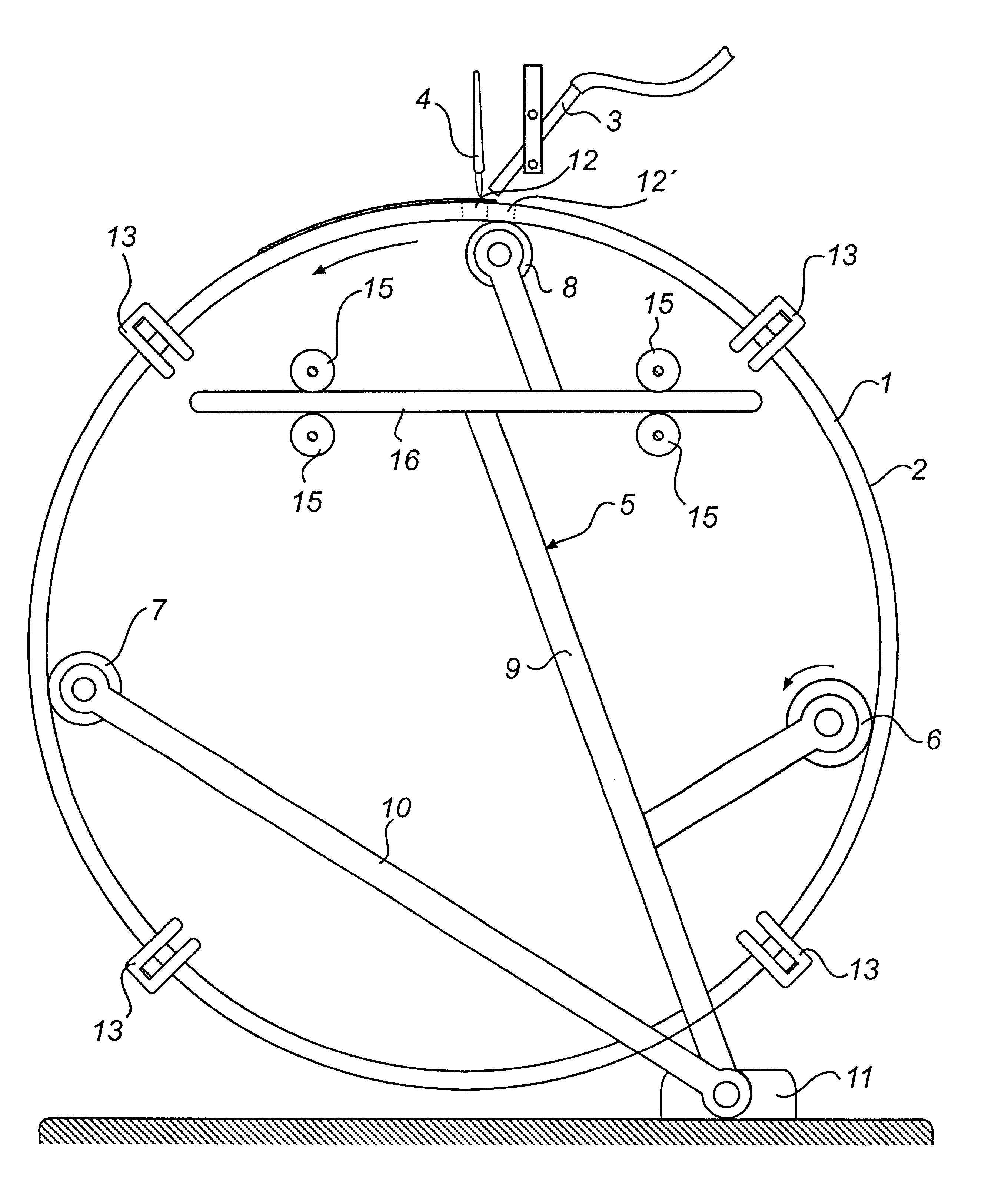
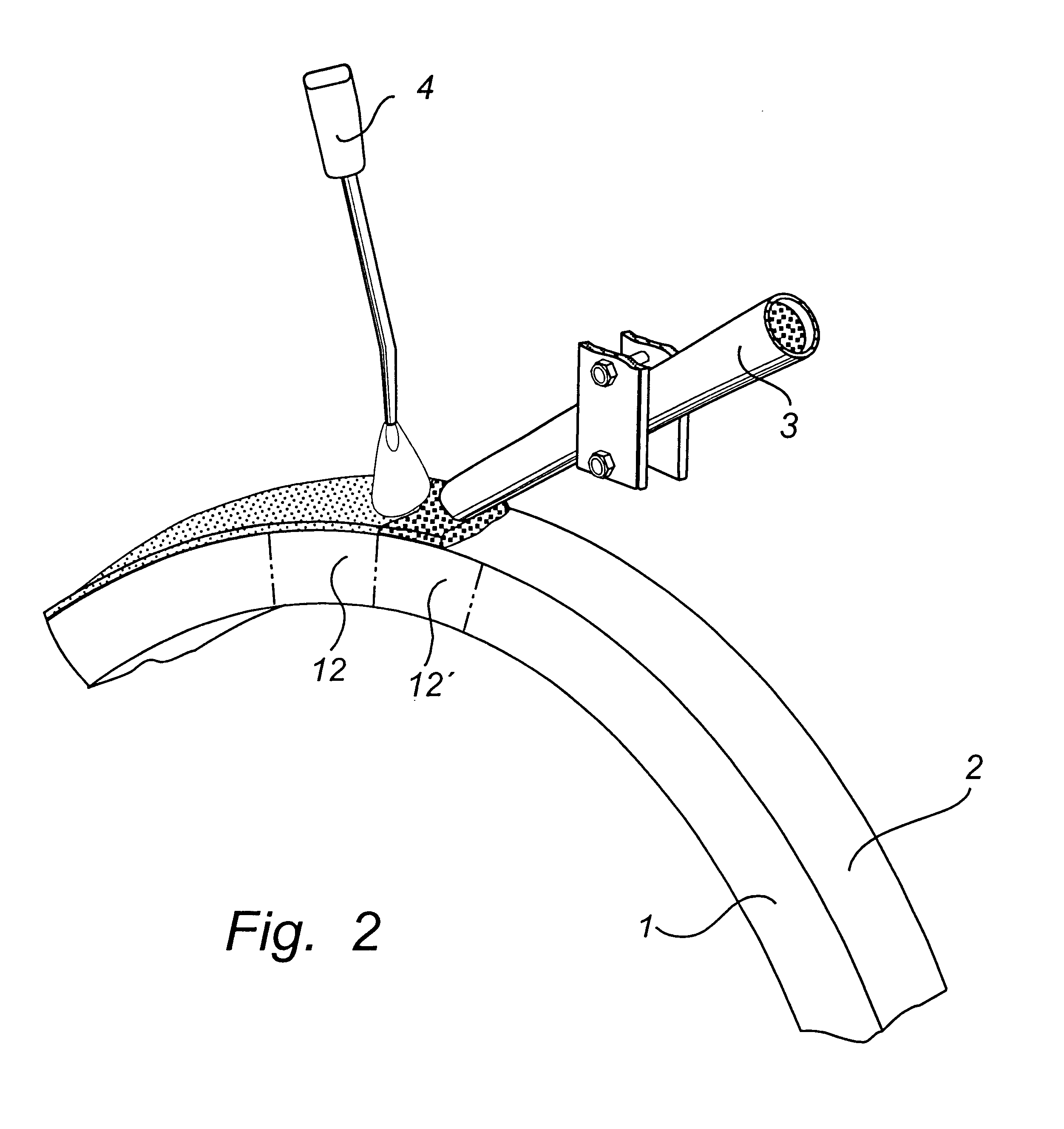
FIG. 1 shows an embodiment of a device according to the invention. A piston ring blank 1 which is to be coated on its outside with a wearing layer is arranged in a device for coating according to the invention. The device comprises a powder feeding means 3 which is associated with a store (not shown) for coating powder. Adjacent to the powder feeding means 3, a laser device 4 is also arranged.

The piston ring blank 1, which has a somewhat oval shape, is supported by a suspension device 5. The suspension device 5 comprises three supporting means 6, 7, 8 against which the piston ring blank abuts. In this embodiment, the supporting means 6, 7, 8 are substantially cylindrical and rotatable on a respective cylinder axis. One of the supporting means 6 is connected to a driving means (not shown), for instance a motor unit, which drives this cylindrical supporting means 6 to rotate in counter-clockwise direction. Due to friction between the supporting means 6 and the piston ring blank 1, als...


PUM

PropertyMeasurementUnit
Percent by massaaaaaaaaaa
Widthaaaaaaaaaa

Abstract

The present invention relates to a method for applying a layer to a piston ring blank, in particular for a piston ring of the kind that is intended for use in large diesel engines. A coating powder is supplied to one of succeeding portions of the piston ring blank, after which the coating powder is melted with the aid of an energy radiation means at a constant distance from the coating powder which was last supplied to the piston ring blank to form a coating layer on said portion of the piston ring blank. The energy radiation is allowed to act on the coating powder for a period of time which is adjusted so that substantially no heat, besides the heat required for melting the powder material develops. The invention also relates to a device for performing the method.

Description

The present invention relates toga method for applying a layer to a piston ring blank, in particular for a piston ring of the kind that is intended for use in large diesel engines.The invention also relates to a device for performing the method.TECHNICAL BACKGROUNDPiston rings of the kind which are preferably used in large diesel engines, for instance in boat engines, are exposed to extreme conditions during the operation of the engine. A high degree of wear, heat and corrosive attack cause the piston rings to quickly wear, thus necessitating replacement.Many methods for increasing the service life of the piston rings have been proposed. Some of these methods are directed to the application of an abrasion-resistant layer to the most exposed portions of the piston ring, preferably its outer periphery. These wearing layers can, for instance, be applied chemically to the ring material by means of an electrolytic reaction or be welded to the same under the action of a heating means, oft...

Claims


Application Information

Patent Timeline
IPC IPC(8): C23C24/10C23C24/00F02F3/10F16J9/26C23C26/00C23C24/08
CPCC23C24/10F02F3/10F16J9/26C23C24/103
Inventor ARAM, MEHDISUNDEN, HANS
Owner KONCENTRA MARINE & POWER
Learn More