
Stack Pointer Management

a technology of pointers and management objects, applied in the field of pointers, can solve problems such as incompatibility between different generations of microprocessors, and achieve the effect of reducing the number of pointers

Inactive Publication Date: 2003-07-22
TEXAS INSTR INC
View PDF3 Cites 9 Cited by
  • Summary
  • Abstract
  • Description
  • Claims
  • Application Information

AI Technical Summary

Problems solved by technology

However, this may result in program incompatibility between different generations of microprocessors.

Method used


Image

  • Stack Pointer Management
  • Stack Pointer Management
  • Stack Pointer Management

Examples


Embodiment Construction

Although the invention finds particular application to Digital Signal Processors (DSPs), implemented, for example, in an Application Specific Integrated Circuit (ASIC), it also finds application to other forms of processors.

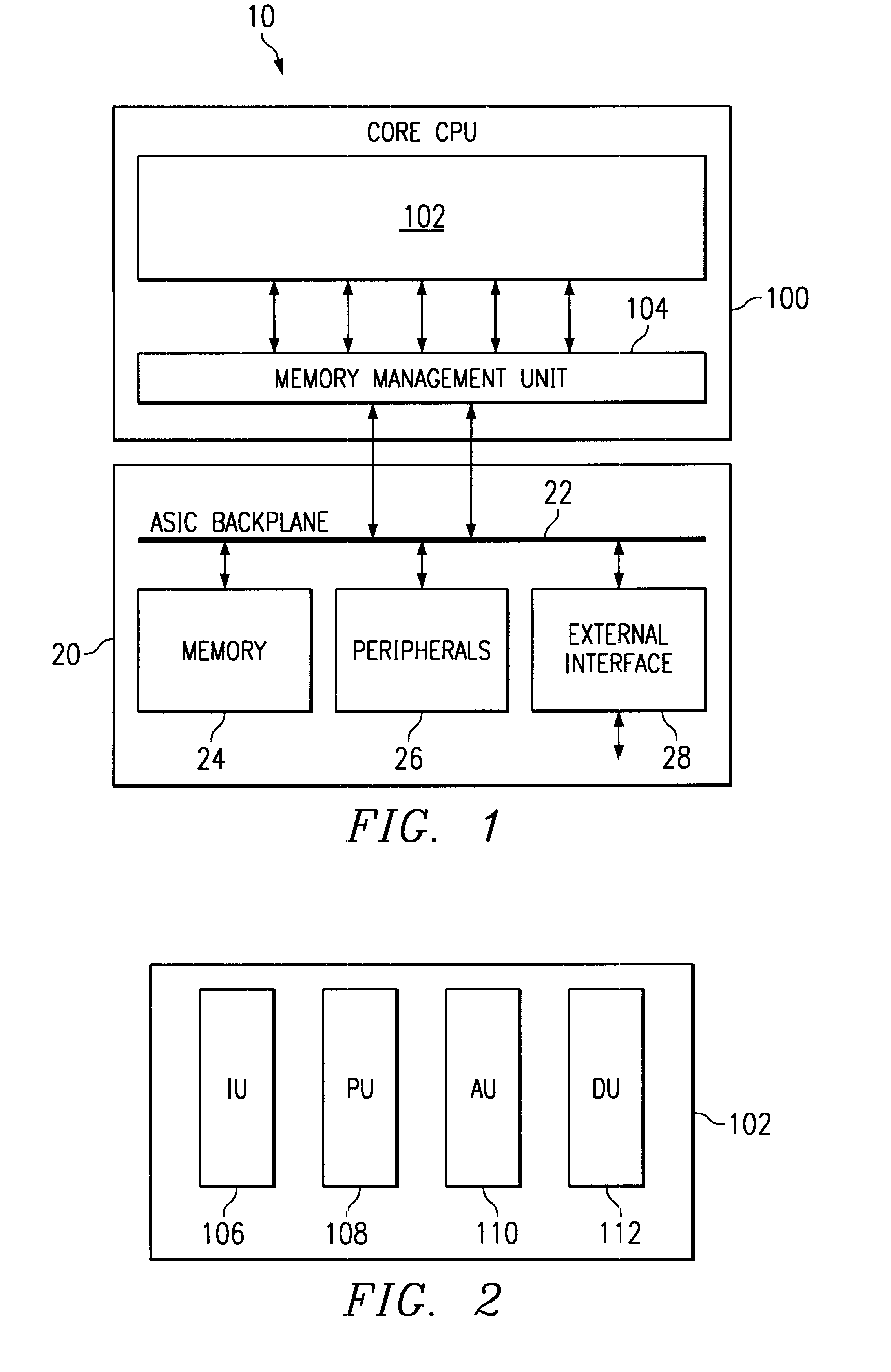
The basic architecture of an example of a processor according to the invention will now be described. Processor 100 is a programmable fixed point DSP core with variable instruction length (8 bits to 48 bits) offering both high code density and easy programming. Architecture and instruction set are optimized for low power consumption and high efficiency execution of DSP algorithms as well as pure control tasks, such as for wireless telephones, for example. Processor 100 includes emulation and code debugging facilities.

FIG. 1 is a schematic overview of a digital system 10 in accordance with an embodiment of the present invention. The digital system includes a processor 100 and a processor backplane 20. In a particular example of the invention, the digital system is...


PUM


Abstract

A processor (100) is provided that is a programmable digital signal processor (DSP) with variable instruction length. A user stack region (910) is used to pass variables to a subroutine and to hold values representative of a first portion of a program counter (1000). A system stack region (911) is used to hold values representative of a remaining portion of the program counter (1001) and to hold additional context information. The user stack region and the system stack region are managed independently so that software from a prior generation processor can be translated to run on processor (100).

Description

This application claims priority to Ser. No. 99400556.9, filed in Europe on Mar. 8, 1999 (TI-27760EU) and Ser. No. 98402455.4, filed in Europe on Oct. 6, 1998 (TI-28433EU).The present invention relates to processors, and to management of a stack for passing variables during the execution of instructions in such processors.Background of the InventionMicroprocessors are general purpose processors which require high instruction throughputs in order to execute software running thereon, and can have a wide range of processing requirements depending on the particular software applications involved. It is known to provide a stack that can be used to pass variables from one software routine to another. Stacks are also used to maintain the contents of the program counter when a first software routine calls a second software routine, so that program flow can return to the first software routine upon completion of the called second routine. A call within the second software routine can call a ...

Claims


Application Information

Patent Timeline
Patent Type & Authority Patents(United States)
IPC IPC(8): G06F9/355G06F7/76G06F9/32G06F9/318G06F5/01G06F9/30G06F7/74G06F9/34G06F9/315G06F7/60G06F9/38H04M1/73H04M1/72G06F7/78
CPCG06F5/01G06F7/607G06F7/74G06F7/762G06F7/764G06F7/78G06F9/30134G06F9/30149G06F9/321G06F9/3004
Inventor LAURENTI, GILBERTJACKSON, WALTER A.ROSENZWEIG, JACK
Owner TEXAS INSTR INC
Learn More