
Implantable medical device incorporating miniaturized circuit module

Inactive Publication Date: 2003-05-20
MEDTRONIC INC
View PDF21 Cites 254 Cited by
  • Summary
  • Abstract
  • Description
  • Claims
  • Application Information

AI Technical Summary

Benefits of technology

and the objects, advantages and features thereof have been presented here simply to point out some of the ways that the invention overcomes difficulties presented in the prior art and to distinguish the inv

Problems solved by technology

Apart from the bulk of the antenna taking up valuable space within the IMD housing, there are a number of other limitations in the current MEDTRONIC.RTM. telemetry system employing the 175 kHz carrier frequency.
First, using a ferrite core, wire coil, RF telemetry antenna results in a very low radiation efficiency because of feed impedance mismatch and ohmic losses and a radiation intensity attenuated proportionally to at least the fourth power of distance (in contrast to other radiation systems which have radiation intensity attenuated proportionally to square of distance).
The time delays between downlink telemetry transmissions depend upon the user of the programmer, and there is a chance that the programmer head will not be held steady.
Secondly, the RF telemetry data transmission rate is limited employing a 175 kHz carrier frequency.
However, the discrete inductor and capacitor components mounted with one or more IC chip to an RF IC module substrate render the RF module unduly large such that it occupies a substantial portion of the volume within the IMD housing.
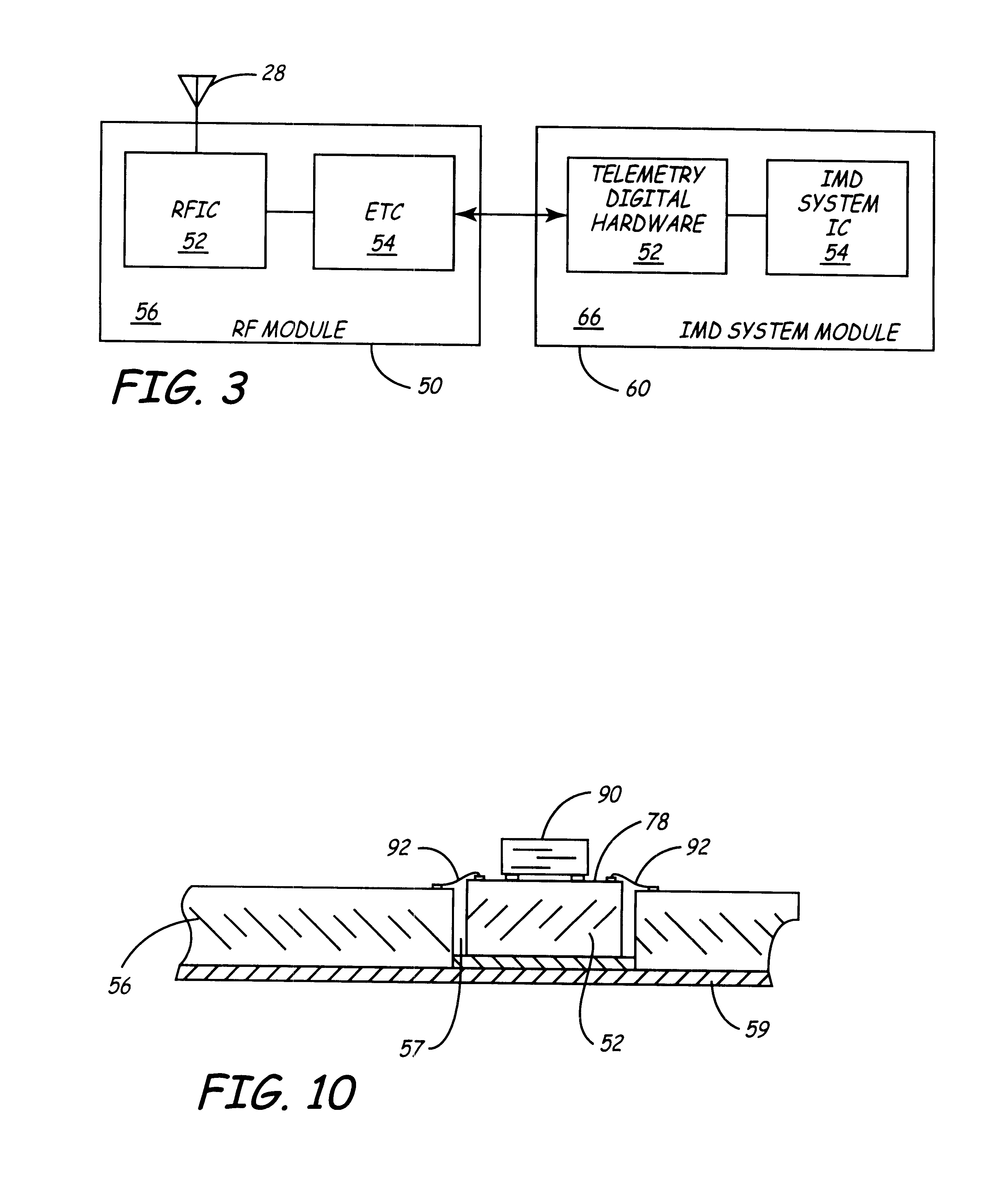
In these ways the form factor of the RF module is decreased, and the space within the IMD housing can be occupied by other components or can result in making the housing itself smaller and possibly thinner in profile than it would otherwise be.

Method used


Image

  • Implantable medical device incorporating miniaturized circuit module
  • Implantable medical device incorporating miniaturized circuit module
  • Implantable medical device incorporating miniaturized circuit module

Examples


Embodiment Construction

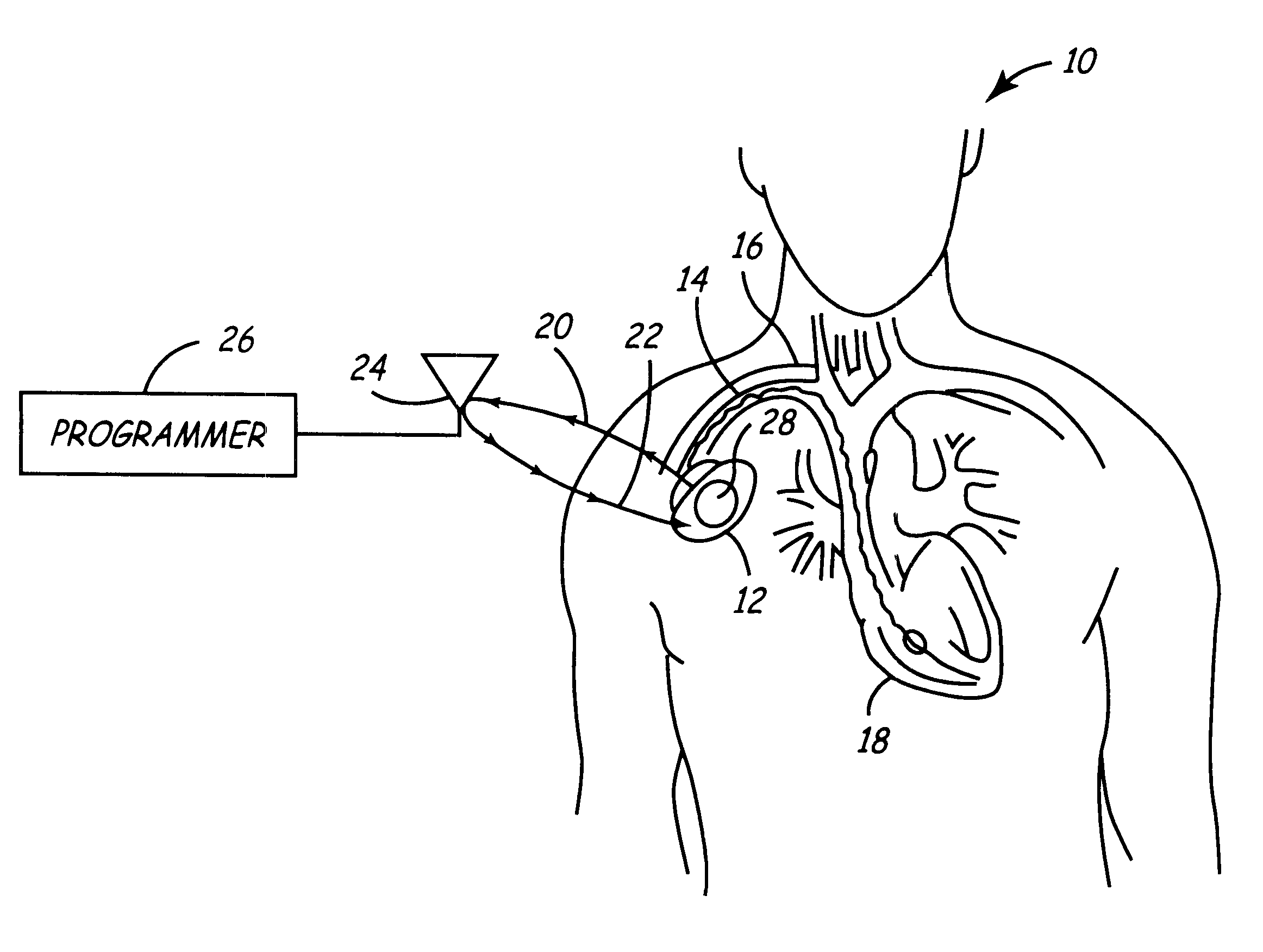
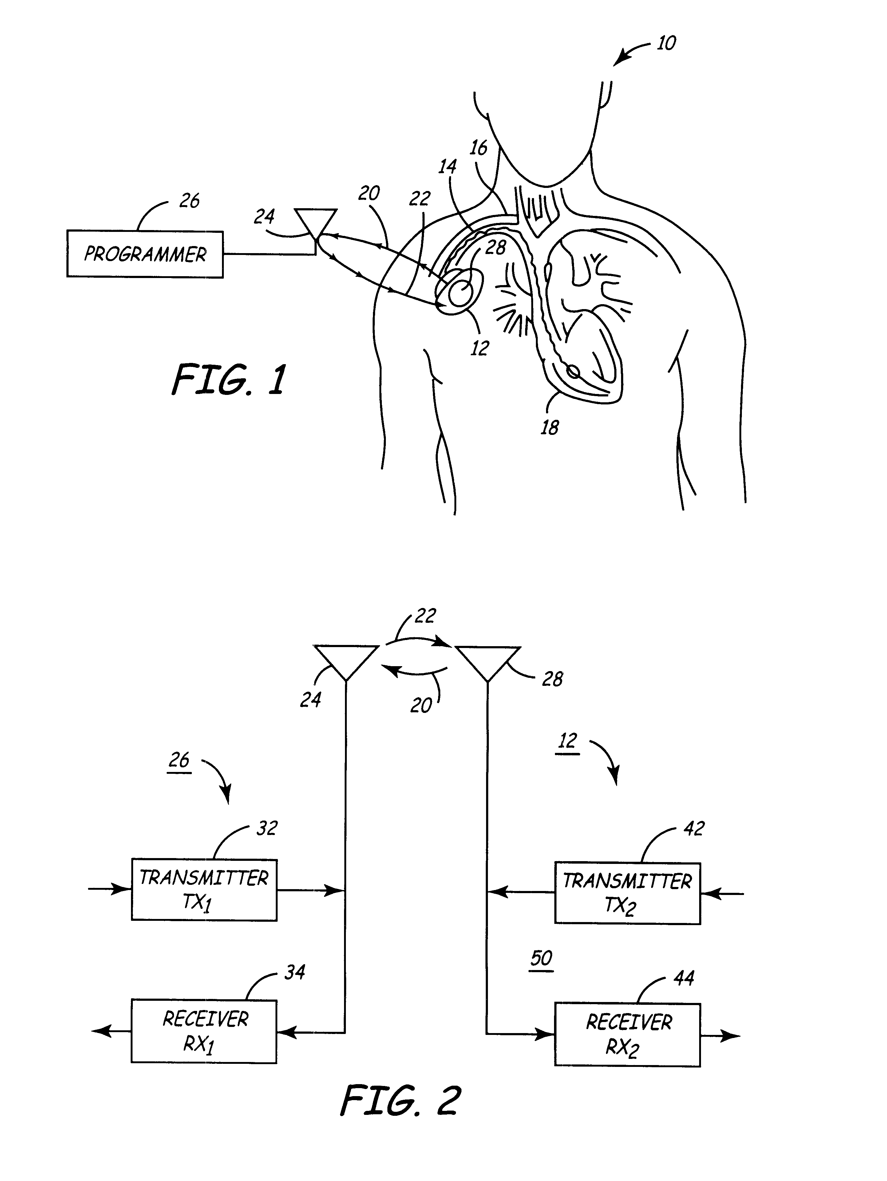
The present invention can be implemented in any IMD having high frequency RF telemetry capabilities. The present invention will be described in relation to a cardiac pacemaker or ICD IPG operating system design, but it is not intended that the invention be limited to that particular application when it can be advantageously implemented in various types of IMDs. At present, a wide variety of IMDs are commercially released or proposed for clinical implantation. Such medical devices include implantable cardiac pacemakers as well as ICDs, pacemaker-cardioverter-defibrillators, drug delivery pumps, cardiomyostimulators, cardiac and other physiologic monitors, nerve and muscle stimulators, deep brain stimulators, cochlear implants, artificial hearts, etc. As the technology advances, IMDs become ever more complex in possible programmable operating modes, menus of available operating parameters, and capabilities of monitoring increasing varieties of physiologic conditions and electrical sig...


PUM


Abstract

Implantable medical devices (IMDS) having RF telemetry capabilities for uplink transmitting patient data and downlink receiving programming commands to and from an external programmer having an improved RF module configured to occupy small spaces within the IMD housing to further effect the miniaturization thereof. An RF module formed of an RF module substrate and at least one IC chip and discrete components has a volume and dimensions that are optimally minimized to reduce its volumetric form factor. Miniaturization techniques include: (1) integrating inductors into one or more IC chips mounted to the RF module substrate; (2) mounting each IC chip into a well of the RF module substrate and using short bonding wires to electrically connect bond pads of the RF module substrate and the IC chip; and (3) surface mounting discrete capacitors over IC chips to reduce space taken up on the RF module substrate. The integrated inductors are preferably fabricated as planar spiral wound conductive traces formed of high conductive metals to reduce trace height and width while maintaining low resistance, thereby reducing parasitic capacitances between adjacent trace side walls and with a ground plane of the IC chip. The spiral winding preferably is square or rectangular, but having truncated turns to eliminate 90° angles that cause point-to-point parasitic capacitances. The planar spiral wound conductive traces are further preferably suspended over the ground plane of the RF module substrate by micromachining underlying substrate material away to thereby reduce parasitic capacitances.

Description

This invention relates generally to implantable medical devices (IMDs) having RF telemetry capabilities for uplink transmitting patient data and downlink receiving programming commands to and from an external programmer, and more particularly to a miniaturized circuit module configured to occupy a small space within the IMD housing to further effect the miniaturization thereof.A wide variety of IMDs that employ electronic circuitry for providing electrical stimulation of body tissue and / or monitoring a physiologic condition are known in the art. A number of IMDs of various types are known in the art for delivering electrical stimulating pulses to selected body tissue and typically comprise an implantable pulse generator (IPG) for generating the stimulating pulses under prescribed conditions and at least one lead bearing a stimulation electrode for delivering the stimulating pulses to the selected tissue. For example, cardiac pacemakers and implantable cardioverter-defibrillators (IC...

Claims


Application Information

Patent Timeline
IPC IPC(8): A61N1/375A61N1/372
CPCA61N1/37223A61N1/3758Y10S977/932Y10S977/94
Inventor THOMPSON, DAVID L.HAUBRICH, GREGORY J.
Owner MEDTRONIC INC
Learn More