
Rod holder and bracket therefor

Inactive Publication Date: 2003-05-13
HAWIE ROBERT L
View PDF15 Cites 73 Cited by
  • Summary
  • Abstract
  • Description
  • Claims
  • Application Information

AI Technical Summary

Benefits of technology

Another object is to provide a fishing rod hanger formed of a pair of cylindrically shaped brackets having a portion thereof defining a pivoting latch for swinging between an open and closed position whereby the latch is positively latched in the closed position, and which is rendered readily releasable.
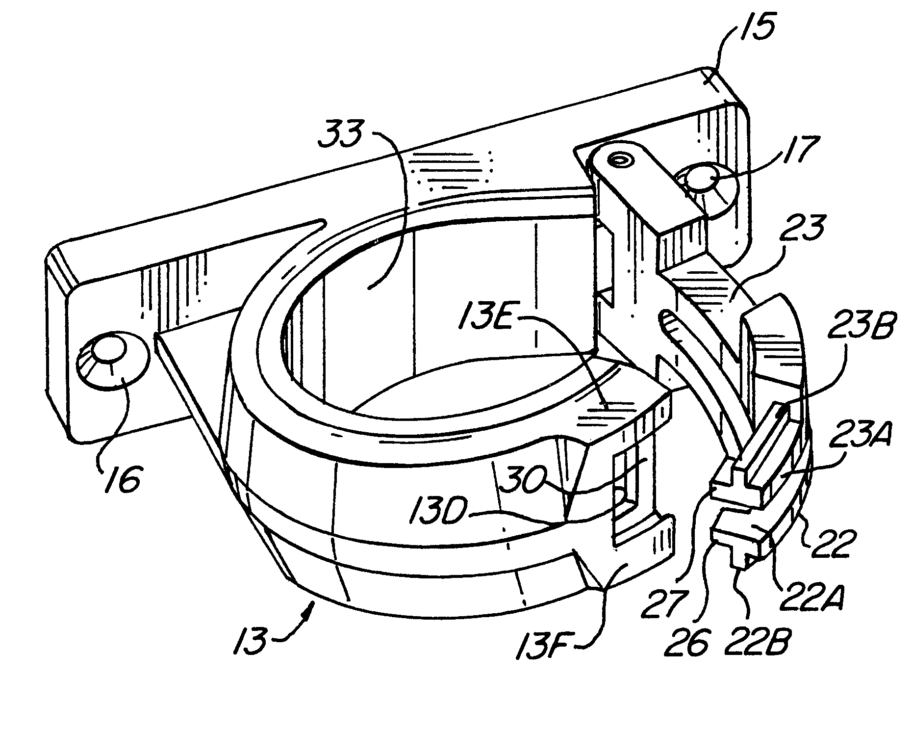
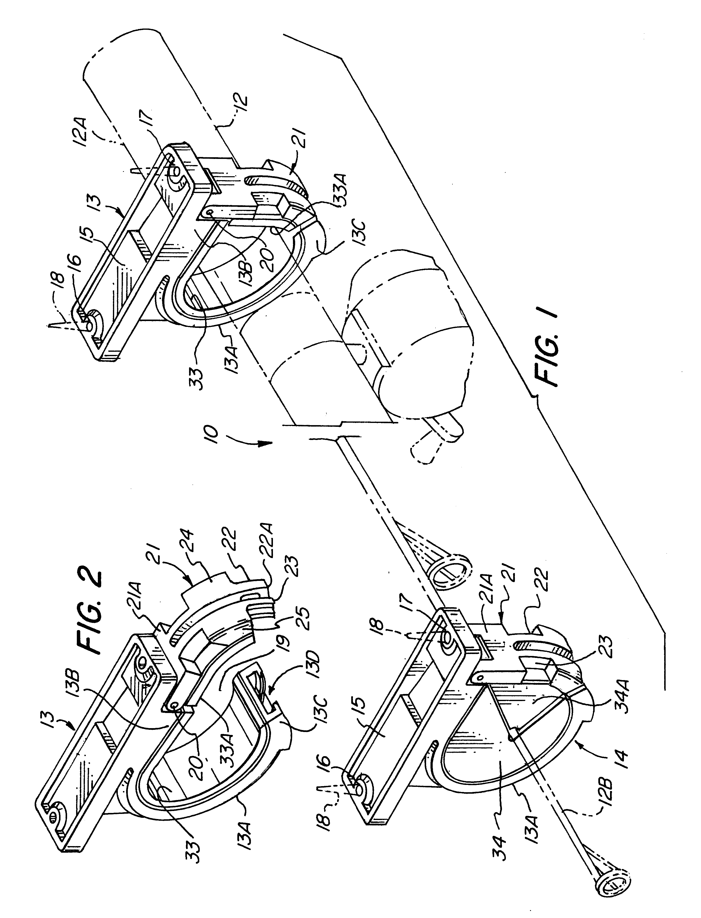
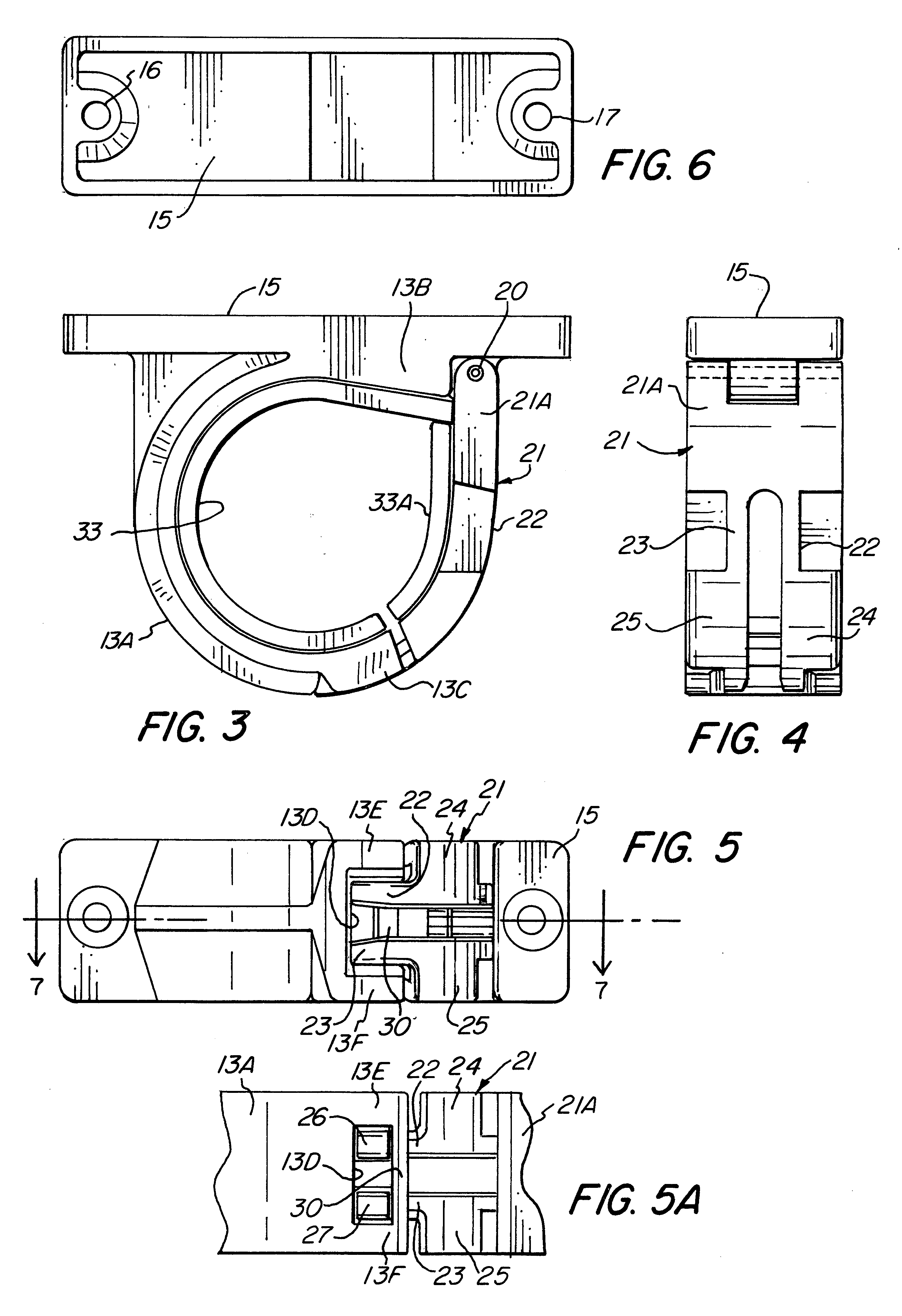
The foregoing objects and other features and advantages are attained by a rod hanger formed of a pair of spaced apart cooperating brackets, each having a mounting base by which the respective brackets may be secured to the supporting surface, e.g. a wall, ceiling, or other suitable supporting surface. Each of the respective brackets are generally circular in shape and include a fixed portion that is generally C-shaped to define an opening and a complementary arcuate shaped latch. The latch is pivotally connected to one end of the fixed C-shaped portion to pivot between an open and closed position and includes a pair of arcuate shaped spaced apart flexible arms adapted to engage a slotted opening formed in the other end of the fixed C-shaped portion. The respective flexible arms include a laterally outwardly extending flange arranged to mate with complementary grooves formed in the slotted opening of the fixed C-shaped portion. Connected to the free end of the respective arms is a catch or detent extending substantially normal relative to its corresponding flexible arm to engage a lip extending transversely between the opposed edges of the slotted opening. In the latched position, the detent or catch engaging the transverse lip in conjunction with the interengagement of the laterally extending flanges within complementary grooves formed in the receiving end of the fixed portion positively secures or locks the latch in the closed position until such time that the flexible fingers are pressed together or squeezed by the application of a positive force. If desired, the internal surfaces of the respective brackets may be lined with a resilient liner or cushion to render a fishing rod supported therebetween immobile to prevent any damage thereto.

Problems solved by technology

However, the known rod holders or supports, while capable of supporting a fishing rod, are relatively complex in structure and sometimes difficult to manufacture which rendered them uneconomical to market.

Method used


Image

  • Rod holder and bracket therefor
  • Rod holder and bracket therefor
  • Rod holder and bracket therefor

Examples


Embodiment Construction

Referring to FIG. 1, there is shown therein a rod hanger 10 embodying the present invention, which is adapted to be attached to any suitable supporting surface (not shown). It will be understood that the rod hanger 10 may be adapted to support varying kinds of rods, e.g. curtain rods, drapery rods, fishing rods and the like. For purposes of description, the rod hanger 10 will be described with reference to a fishing rod 12, shown in phantom in FIG. 1. As it will be apparent, the rod hanger 10 may be supported on any suitable surface, e.g. a wall, ceiling, gunwale of a boat, railing or any other suitable supporting surface.

As evident in FIG. 1, the rod hanger 10 comprises at least a pair of brackets 13 and 14 disposed in spaced relationship. Each of the respective brackets 13 and 14 are generally similar in structure. Referring to FIGS. 1 to 3, each of the respective brackets 13 and 14 include a mounting plate 15--15 provided with opposed through holes 16 and 17 by which the respecti...


PUM


Abstract

A rod hanger which includes a pair of similarly constructed brackets, each having a mounting plate and a connected generally C-shaped portion connected thereto defining an opening and a complementary latch pivotally connected to one end of the fixed portion to swing between open and closed position. The latch includes a pair of flexible arms provided with opposed outwardly extending flanges and a catch detent formed at the free ends thereof whereby the flanges are arranged to engage in complementary grooves formed in the other end of the C-shaped portion, and the catch detent engaging a transversely extending lip so as to prohibit any unintentional unlatching of the latch. The arrangement is such that the latch is rendered self-locking in the closed position, and rendered readily releasable upon the application of a positive squeezing force on the flexible arms. A resilient liner or cushion secured to the inner surface of the brackets maintains the alignment and protection of a rod, e.g. a fishing rod, supported therebetween from damage.

Description

This invention relates to a rod holder or support, and more specifically to a rod holder comprising a pair of spaced apart brackets, each having a releasable and self-locking latch that is positively locked in the latched position for releasably holding and positively securing a rod therebetween.A wide variety of rod holders are known. Heretofore, the known rod holders, and particularly those for supporting a fishing rod, were commonly designed or constructed so that the handle portion of a fishing rod was supported or received in one bracket and the other end of the rod supported in a complementary bracket. The respective brackets included a latch shiftable between an open or closed position. Examples of such supports are illustrated in U.S. Pat. Nos. 3,672,513; 4,006,825 and 4,109,796.Other known examples of rod holders are disclosed in U.S. Pat. Nos. 4,986,504; 4,586,688; 4,170,801; 4,132,381; 3,995,742 and 3,643,811. However, the known rod holders or supports, while capable of s...

Claims


Application Information

Patent Timeline
IPC IPC(8): A01K97/10F16M13/02
CPCA01K97/10F16M11/041F16M13/02
Inventor HAWIE, ROBERT L.
Owner HAWIE ROBERT L
Learn More