
Magneto-acoustic imaging

a magnetic and acoustic imaging technology, applied in the field of magnetic acoustic imaging, can solve the problems of distorting the image produced, expensive and bulky apparatus in all these cases, and difficult to use remote locations,

Inactive Publication Date: 2003-03-18
MAGNETUS
View PDF6 Cites 93 Cited by
  • Summary
  • Abstract
  • Description
  • Claims
  • Application Information

AI Technical Summary

Benefits of technology

The method provides different information about the body than conventional ultrasound or MRI, in that here the primary feature imag...

Problems solved by technology

The apparatus in all these cases is expensive and bulky because of the large DC magnetic fields used.
Because of the cryogenics needed to support the DC field currents, the machines are awkward for use in remote locations.
However, these large variation deflect the paths of the microwaves traversing the body and thus distort the image produced.
This effect also causes variable concentration of microwave power dosage in organs.
This process is unstable in the sense that a small change in the observations produces large changes in the computed image.
To avoid the application of electrodes to the body, alternating magnetic fields have been used to produce images from currents in a phantom and a human thorax during respiration ("Magnetic impedance tomography" Ann N Y Acad Sci Apr. 20, 1999; 873:353-9, Tozer J. C., Ireland R. H., Barber D. C., Barker A. T.) A problem with magnetic detection at sub-microwave frequencies is its inherently low resolution, MRI avoids this problem because of the spatially-dependent resonant frequencies which define position.

Method used


Image

  • Magneto-acoustic imaging
  • Magneto-acoustic imaging
  • Magneto-acoustic imaging

Examples


Embodiment Construction

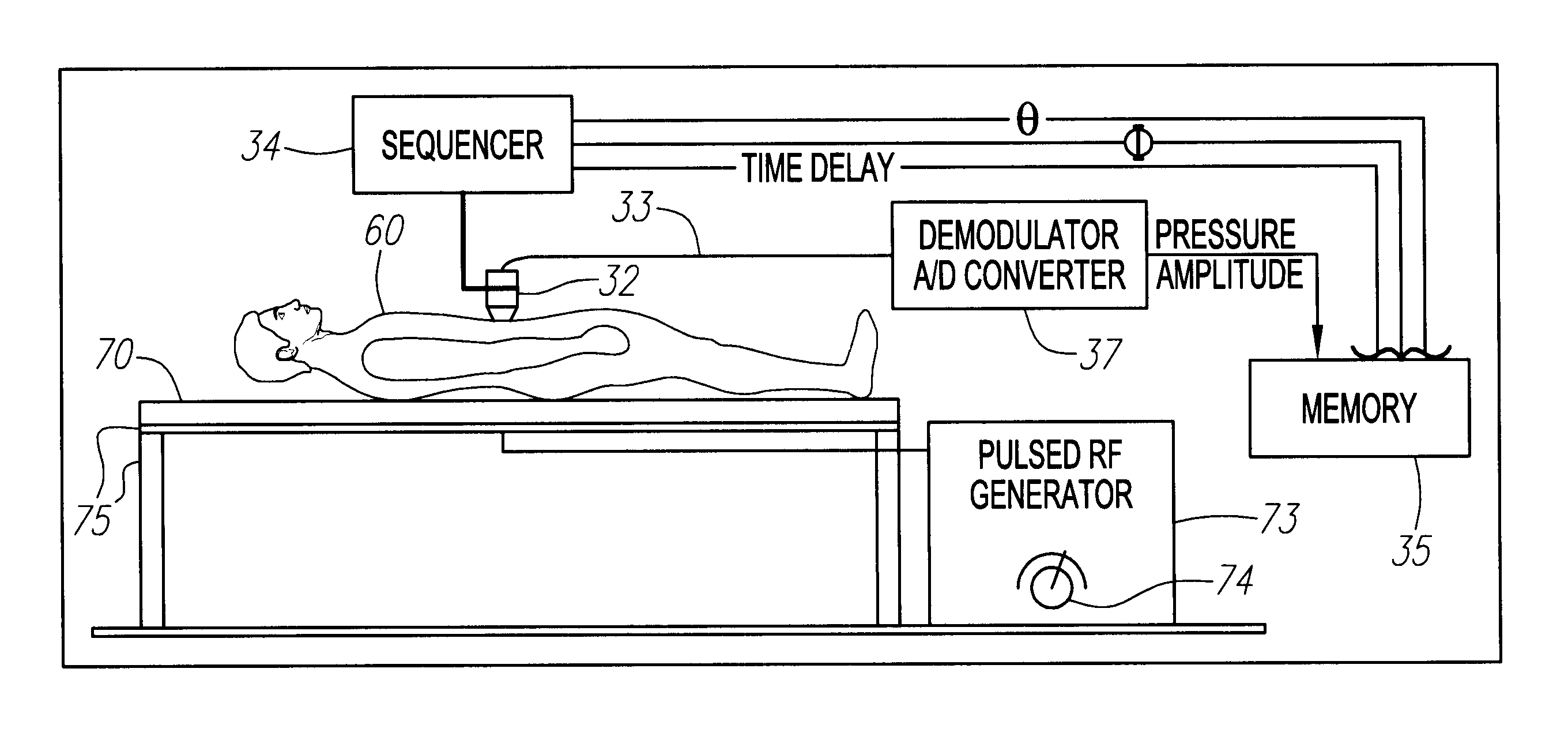
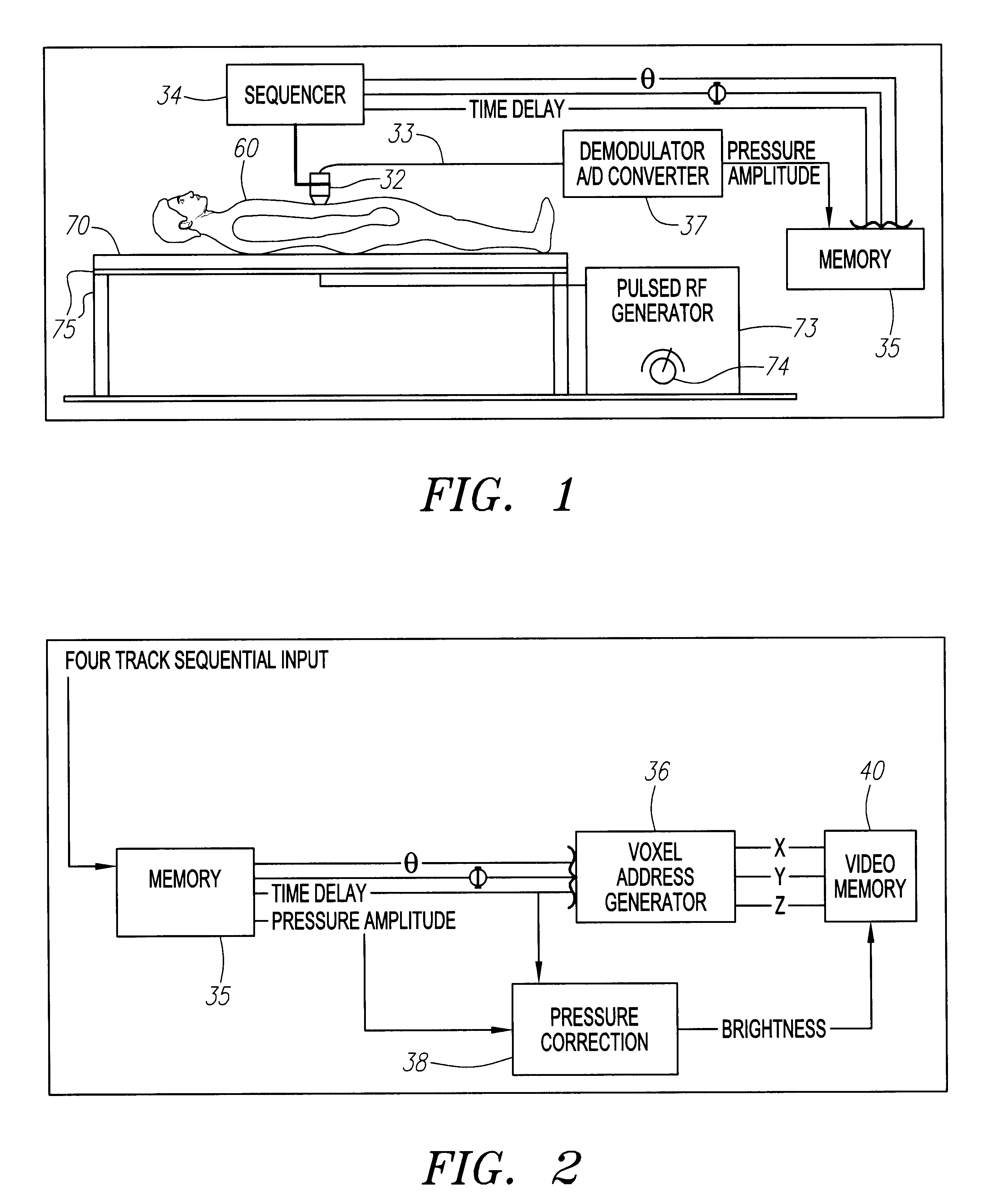
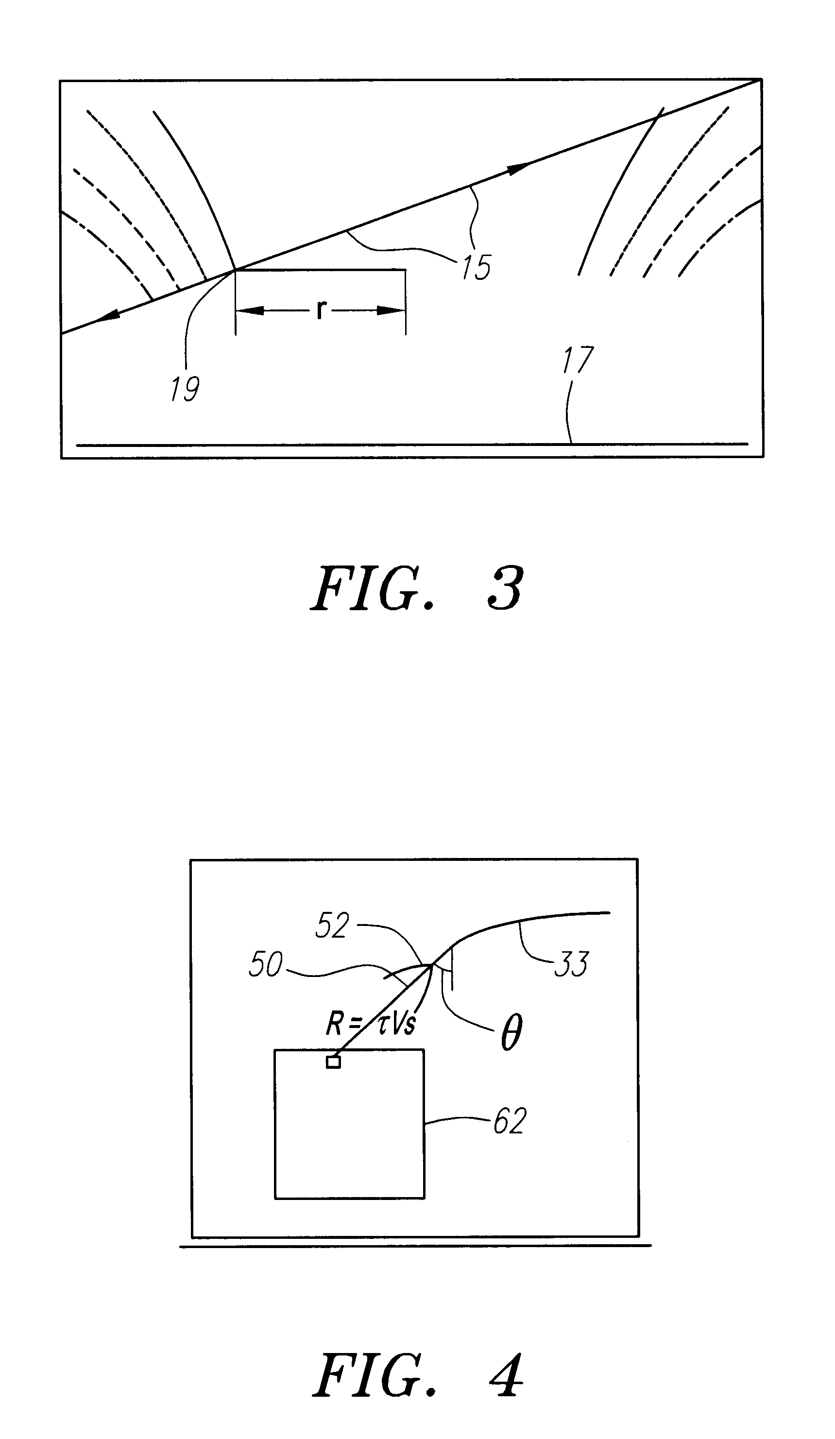
FIG. 1 shows current from a pulsed RF generator 73, driven through a coil 21, underneath a patient 60, lying on a water bed mattress 70, supported by table 75. FIG. 3 plots some fringing RF magnetic field lines (radius vs height) above the coil 17, shown as a dark horizontal line at the bottom of the figure.

We consider the generation of ultrasound from nonresonant RF EM fields. The mechanism consists in the generation of Ohmic currents from the electric field portion of the RF EM field, the currents in turn interacting with the magnetic field (either the magnetic portion of the RF field and / or a background static field) to generate ultrasound. In the latter case, sizable ultrasound imaging signals will be generated at both the RF frequency and at twice the RF frequency, whereas in the absence of a static magnetic field, ultrasound imaging signals will be generated at twice the RF frequency only.

The method provides different information about the body than conventional ultrasound or ...


PUM


Abstract

An apparatus having a coil of wire, energized by a repetitively pulsed radio frequency (RF) power source to provide electromagnetic fields to a region within a body. A scanning, directional hydrophone acoustically connected to the body, samples ultrasonic radiation generated by the RF fields at the RF frequency or twice the RF frequency induced from conductive spots. Signals from the hydrophone are analyzed with regard to their time of arrival relative to the RF pulses and with respect to their direction of arrival. These collected data are recorded and displayed as images of the spots within the region.

Description

1. Field of the InventionThe present invention relates primarily to medical diagnostic equipment generating RF fields and using directional ultrasonic detectors, it can also be applied to characterization of materials and components in non-medical fields.While the present invention is described herein with reference to illustrative embodiments for particular applications, it would be understood that the invention is not limited thereto. Those having ordinary skill in the art and access to the teaching provided herein will recognize additional modifications, applications, and embodiments within the scope thereof and additional fields in which the present invention would be of significant utility.2. Description of Related ArtRadio frequency (RF) electromagnetic (EM) fields are widely used for medical diagnostics in magnetic resonance imaging (MRI). In MRI, RF is used to excite coherent precession of nuclear magnetic moments in a strong static background magnetic field. These processin...

Claims


Application Information

Patent Timeline
IPC IPC(8): A61B5/05A61B8/08G01S7/52A61B5/053G01R33/561
CPCA61B5/05A61B5/416G01S7/52017A61B8/08A61B5/0536G01S7/52034G01R33/56308
Inventor CHANG, DAVID B.DRUMMOND, JAMES E.EMERSON, JANE F.
Owner MAGNETUS
Learn More