
Co-generation system employing a stirling engine

Inactive Publication Date: 2003-02-25
WHISPER TECH
View PDF16 Cites 54 Cited by
  • Summary
  • Abstract
  • Description
  • Claims
  • Application Information

AI Technical Summary

Benefits of technology

the water storage tank being adapted to contain therein the engine and generator in fluid isolation from the primary water within the storage tank, said tank and primary water providing means to reduce noise and vibration of the co-generation system.

Problems solved by technology

However, as discussed by Meijer in U.S. Pat. No. 5,074,114, such engines have a short life and high maintenance costs.
However there are two problems of co-generation systems that are not addressed in any of the known co-generation systems disclosed above.
The first of these is the sometimes unacceptable noise and vibration of the engine within the system.
Further, none of the prior art discloses a system that is of a size to be usable in a mobile situation, for example, in a vehicle designed for living in, or a yacht.
However this closed system uses only a forced air heater, or an air conditioner.

Method used


Image

  • Co-generation system employing a stirling engine
  • Co-generation system employing a stirling engine
  • Co-generation system employing a stirling engine

Examples


first embodiment

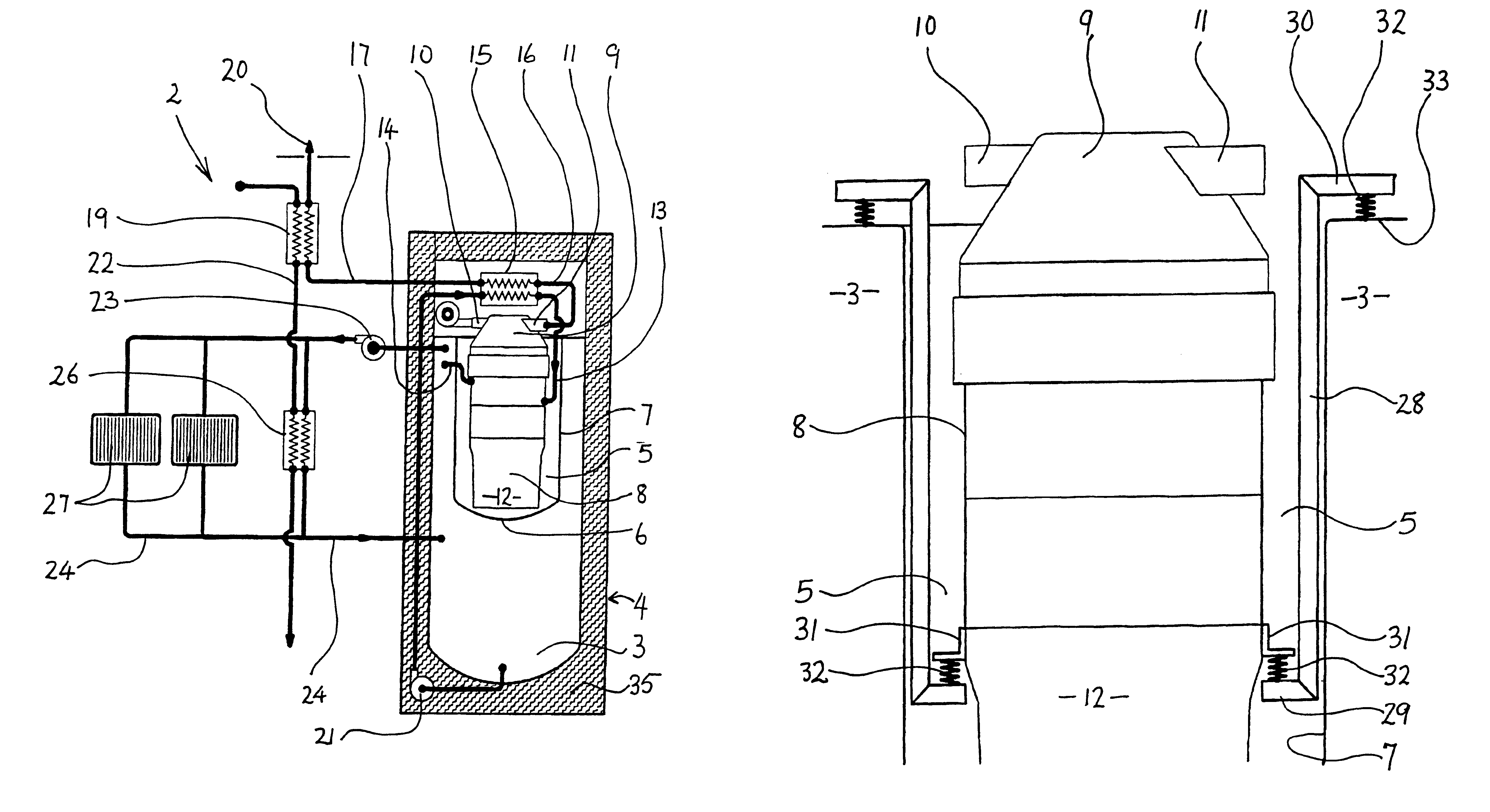
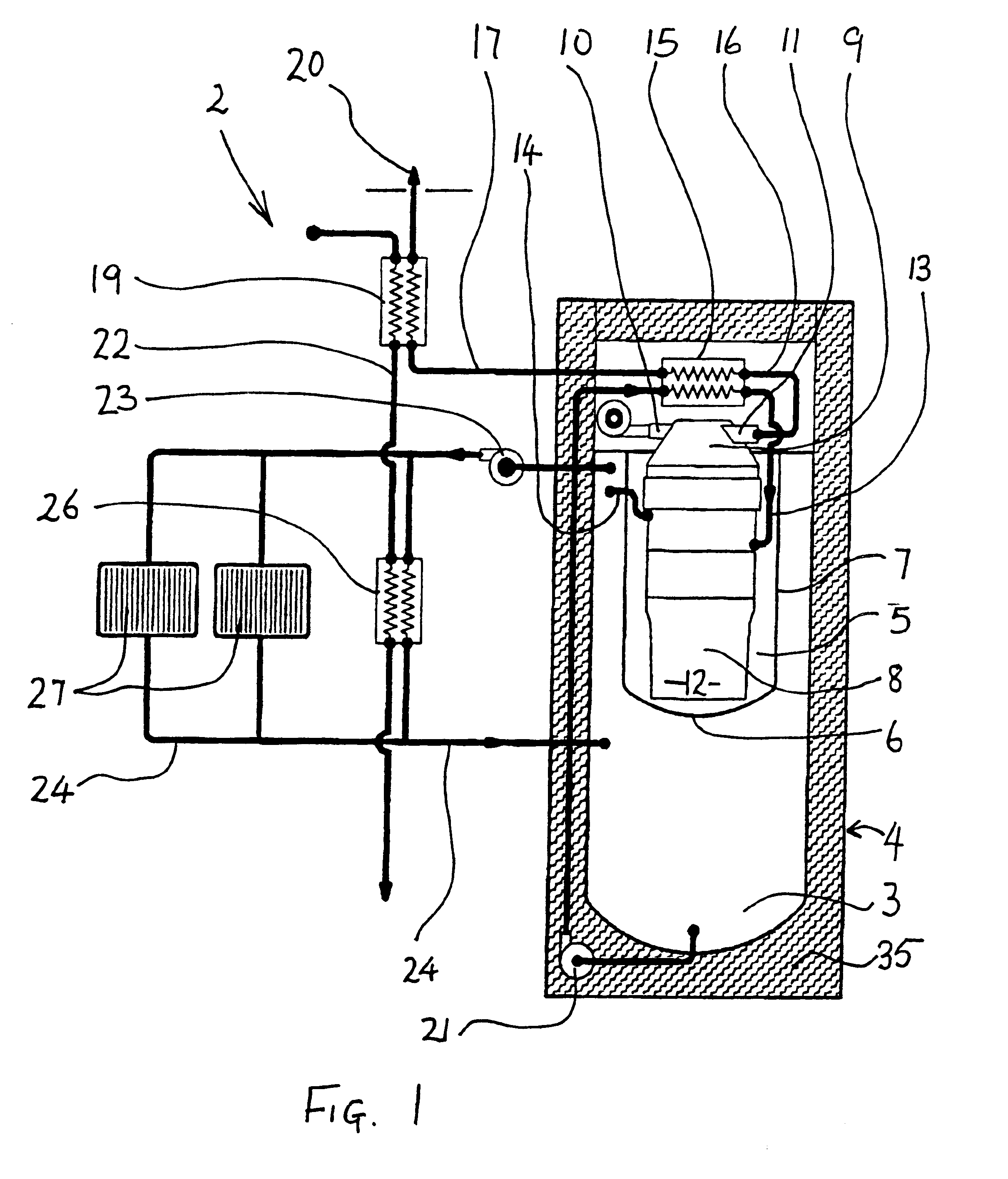
In this first embodiment of the co-generation system 2, the direction of the primary water from the storage tank 3 is as follows: from storage tank 3 the water is moved via the pump 21 to the first heat exchanger 15. From the first heat exchanger 15 the partially heated primary water is transferred through the primary pipe 13 to act as coolant water for the engine 8. From the engine 8, the primary pipe 14 carries the fully heated primary water to the storage tank 3 where it is stored until used in the space heating reticulation as described below.

The heated primary water stored in the storage tank 3 is used for space heating, in known manner, in a reticulation system in the building, by the operation of a pump 23, a secondary pipe 24 and water space heaters 27. With appropriate valves and taps (not shown) a water / water heat exchanger 26 can be switching into this reticulation system. The water / water heat exchanger 26 is used to further heat potable hot water for later use. In additi...

second embodiment

the co-generation system 102 is shown in FIG. 3. Like numbered parts, performing in similar manner, or being the same as in the first embodiment of the co-generation system 2, have the same number.

In this embodiment, the heat exchange in the reticulation system occurring between the primary water in the storage tank 3 and the water space heaters 27 and heat exchanger 26 is identical to the arrangement in the first preferred co-generation system 2. However, the arrangement of heat exchange of the primary water with the exhaust gas and the engine 8 cooling is altered to a second preferred embodiment.

In this second embodiment of the co-generation system 102, the primary water from storage tank 3 leaves storage tank 3 via the pump 21 and enters the engine 8 to act as the engine 8 coolant. The primary pipe 114 transfers the partially heated primary water to the first heat exchanger 15. The primary pipe 113 transfers the now fully heated primary water back to the storage tank 3.

Thus, in t...

third embodiment

In this third embodiment of the co-generation system 202, the movement of the primary water from the storage tank 3 to the engine 8, and from the storage tank 3 to the space heating reticulation by the pump 23 ensures movement of the water within the storage tank 3, so that layering of heat within the storage tank 3 does not occur. This ensures that the heat exchange via heat exchanger 215 operates at the maximum possible efficiency. The coil heat exchanger 215 is shown in FIG. 4 as being immediately adjacent the engine 8 within the storage tank 3. However, it will be appreciated that the placement of the coil heat exchanger 215 may be at any point within the storage tank 3 for convenience and maximum efficiency of operation.

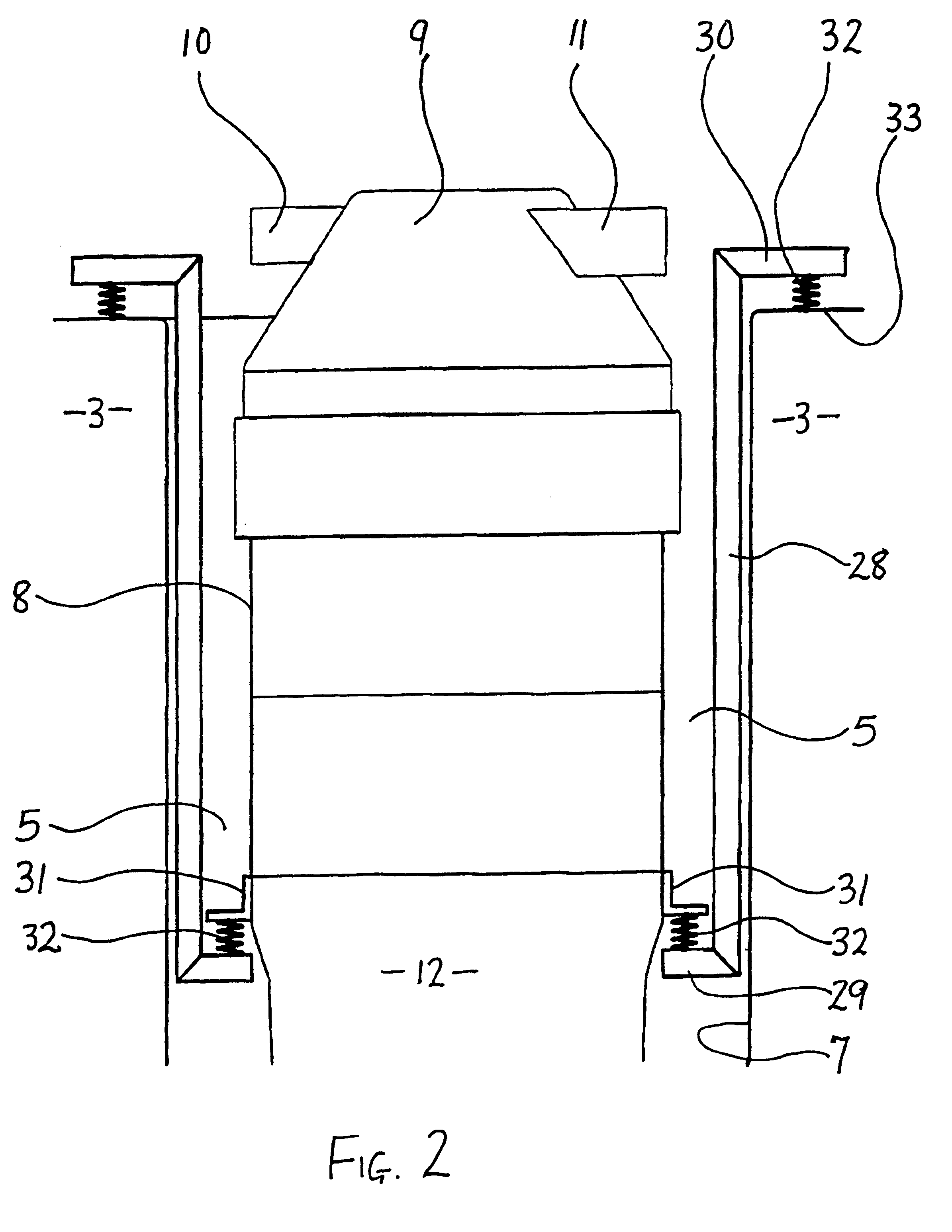
In the second and third embodiments (FIGS. 3 and 4) the mounting of the engine 8 is as described above for the first preferred embodiment of the co-generation system 2.

The co-generation system (2, 102, 202) has been described with reference to a Stirling engine ...


PUM

PropertyMeasurementUnit
Forceaaaaaaaaaa
Heataaaaaaaaaa

Abstract

A co-generation system for producing heat, hot water and electricity for a building is provided while generating a minimum of noise and vibration within the building. The system includes an engine and burner with a generation; a storage tank, for storage of primary water, which is adapted to contain therein the engine and generator; apparatus for circulating and heating the primary water, and apparatus for venting exhaust gases to the outside of the building. The hot water may also be secondary water and either or both water may be potable. The engine optimally operates on a Stirling cycle. The building may be a commercial or domestic dwelling which is free standing or part of a larger structure or may be mobile.

Description

The present invention relates to improvements in co-generation systems, and more particularly in systems that can be used in domestic or small commercial settings.Co-generation is generally defined as a process where an engine is used to generate both heat and electrical power. It also generally refers to the use of the waste heat from the engine as the source of heat for space heating of the dwelling in which the process occurs. Also, the space heating is either by use of hot water in space heaters or by forced air heaters.Example of prior art of co-generation system can be seen in U.S. Pat. No. 4,680,478 (Wicks) and subsequent articles in Popular Science, such as "Home-size Co-generator" by V. Gilmore, on this invention by Wicks. The co-generation system disclosed uses an internal combustion engine and a forced air heat exchanger. However, as discussed by Meijer in U.S. Pat. No. 5,074,114, such engines have a short life and high maintenance costs.Alternatives to the internal combu...

Claims


Application Information

Patent Timeline
IPC IPC(8): F02G5/00F02G1/00F02G1/04F02G5/02F02G1/043F24D11/00F24D18/00
CPCF02G1/04F02G1/043F02G5/02F24D11/002F05C2225/08Y02T10/166F24D2200/26F24H2240/04F28D2020/0078Y02B10/70Y02E20/14F24D2200/04Y02T10/12F24D18/00F24D2103/17F24D2103/13F24D2105/10F24D2101/80
Inventor CLUCAS, DONALD MURRAYAITKEN, MURRAY BRUCE
Owner WHISPER TECH
Learn More