
Method and device for improving the coating surface of strips of paper

Inactive Publication Date: 2003-02-18
BTG ECLEPENS
View PDF16 Cites 12 Cited by
  • Summary
  • Abstract
  • Description
  • Claims
  • Application Information

AI Technical Summary

Benefits of technology

The above objects have been achieved according to the invention by the combination of the following method steps. First, the charge status or charge polarity of the paper web and of the coating mass are ascertained. Second, the web is passed through the nip between two rollers forming part of a film press or metering size press that performs the coating at a web speed of at least 800 m per minute. Third, the paper web or the coating mass or both are so charged that each has a polarity opposite to the polarity of the other. Fourth, as the coating proceeds in the film press, the opposing charges or polarities generate attraction forces that oppose or counteract the above mentioned coating disturbing forces that are effective in the nip exit area downstream of the nip as viewed in the moving direction of the paper web. The attraction forces thus reduce or even eliminate the above mentioned spray fog and orange peel effects.
The present method is performed by an apparatus according to the invention which is characterized by the following features: a coating station including at least one coating film press for coating at least one surface of said paper web with said coating mass, said film press comprising two rollers forming a nip and nip exit area downstream of said nip as viewed in a moving direction of said paper web through said film press, a drive for moving said paper web through said nip and nip exit area in said moving direction at a web speed of at least 800 meters per minute, and an electric charging device positioned for ionizing at least one of said paper web and said coating mass with a charge polarity so that said paper web and said coating mass have opposing charge polarities at least in said nip exit area for acting against coating disturbing forces tending to disturb said coating mass on said paper web in said nip exit area to reduce spray fog and orange peel effects.
The invention has the advantage that with this method using an aqueous coating mass a more closed that is a smooth surface of the coating is achieved which in turn results in an improved printability of the paper. Furthermore, one achieves with the method according to the invention a printability that was possible heretofore only with thicker coatings. As a result, according to the invention printing products can be produced having a lower mass or weight per square. Since these film presses apply the aqueous coating mass, thinner coatings have been made possible, whereby the printed matter produced with such thinner coatings can be advantageously disposed in an environmentally friendly manner.
Furthermore, due to the suppression of the spray fog, less coating mass and fewer cleaning stops are required for the coating equipment, whereby the costs of the thus-coated papers can also be reduced.

Problems solved by technology

When the paper web coated with the coating mass or paint, exits from a nip between the rollers of the film press, a splitting or separation of the coating mass film occurs due to coating disturbing forces generated in the nip exit area because at least some of the coating mass tends to stay on the coating roller rather than be transferred to the web being coated.
The coating mass is more or less viscous and known rheologic problems occur due to said coating disturbing forces which lead to so-called flow lines or to the orange peel effects which reduce the quality of the coating.
Moreover, such film presses run with a speed of 800 to 2000 m / min., whereby small coating mass particles pass as free fog or spray fog into the space just downstream of the nip where the coating mass splits apart on its way from the wetted roller to contact the paper web due to said speed which increase the coating disturbing forces.
However, these efforts have not led to satisfactory results in practice.
Fourth, as the coating proceeds in the film press, the opposing charges or polarities generate attraction forces that oppose or counteract the above mentioned coating disturbing forces that are effective in the nip exit area downstream of the nip as viewed in the moving direction of the paper web.

Method used


Image

  • Method and device for improving the coating surface of strips of paper
  • Method and device for improving the coating surface of strips of paper
  • Method and device for improving the coating surface of strips of paper

Examples


Embodiment Construction

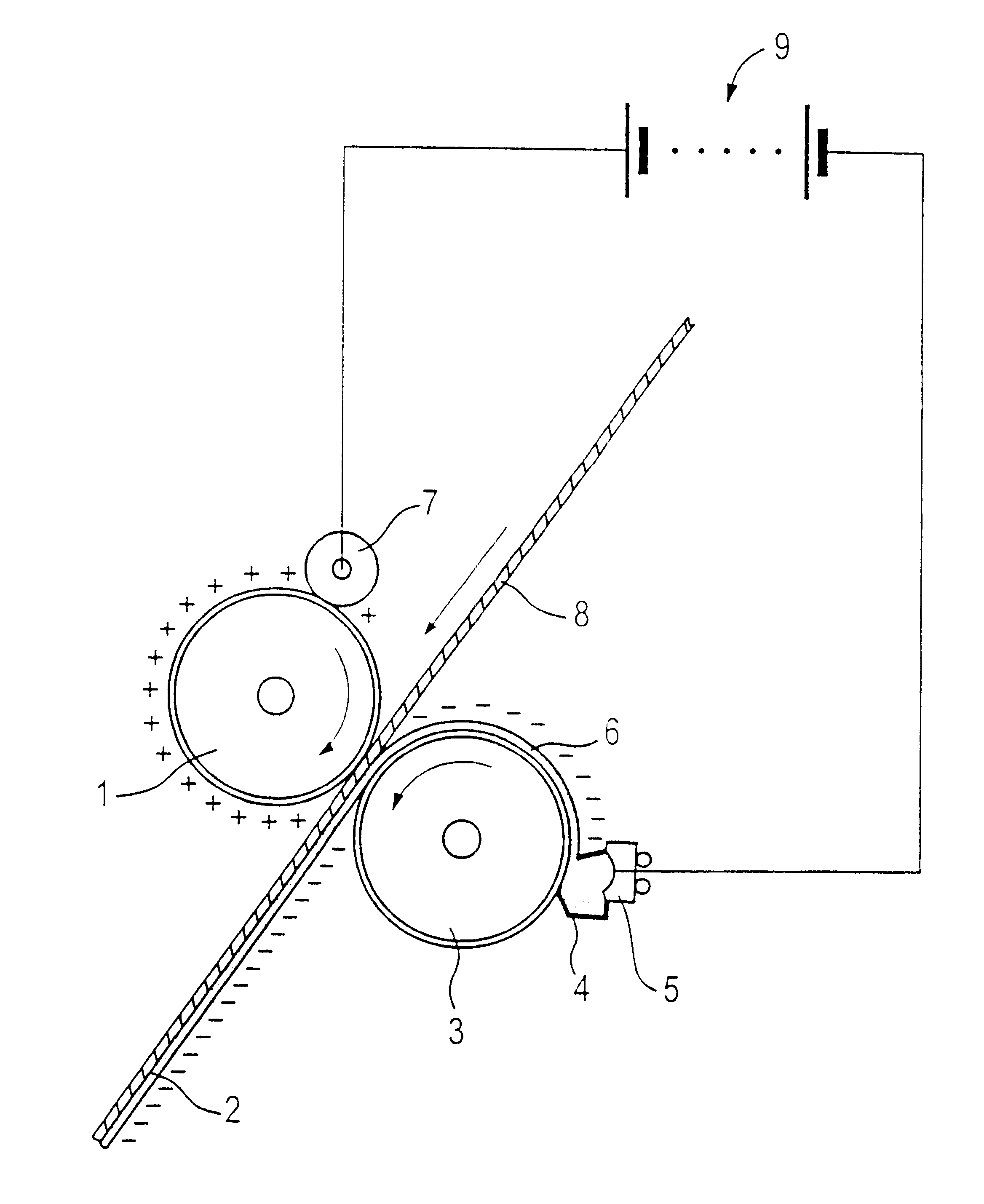
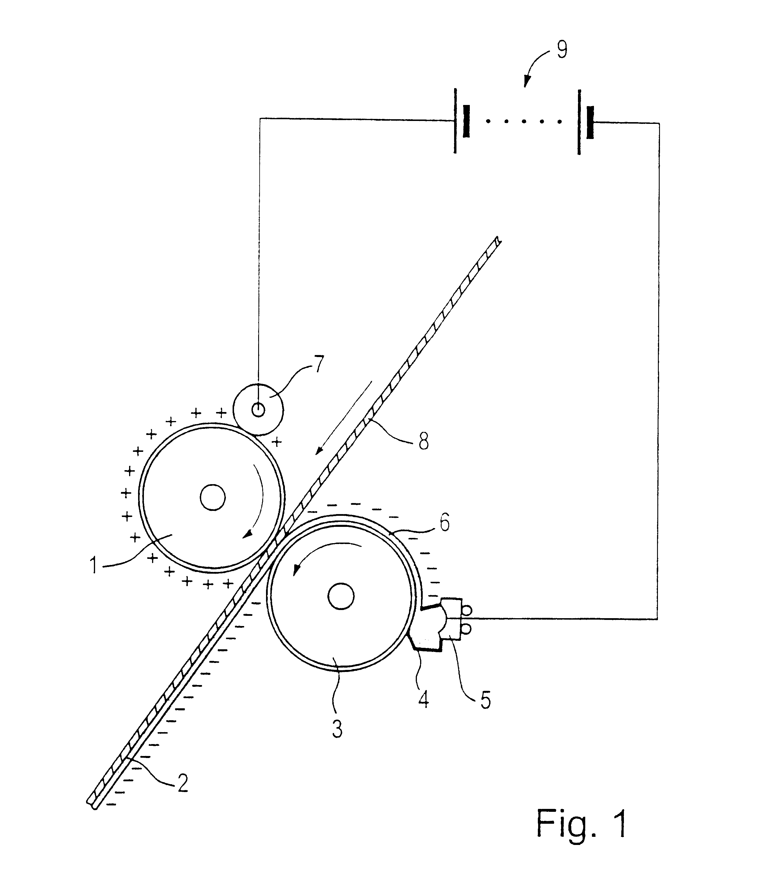
FIG. 1 of the drawing shows a schematic film press. A paper web 8 passes through a film press, whereby the paper web is coated on one side for example with an anionic aqueous coating mass 6. A counter roller 1 cooperates with a coating roller 3. The counter roller 1 is positively ionized by an electric charging device, whereby the counter roller 1 becomes attractive for the anionic aqueous coating mass 6.

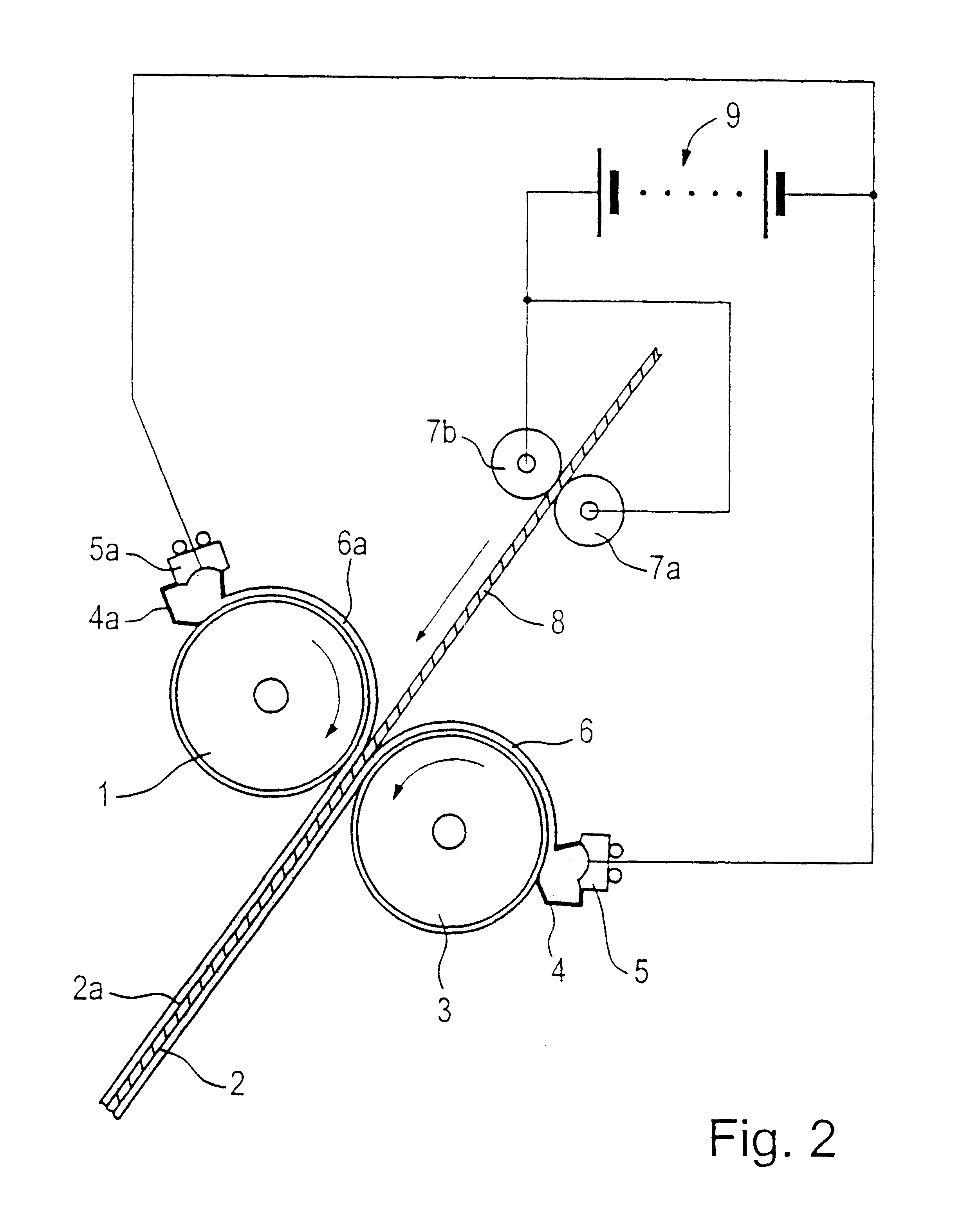
The counter roller 1 and the coating roller 3 of the film press form two film pressing rollers of which the lower roller forms the coating roller 3 and the upper roller forms the counter roller 1. Both rollers 1 and 3 are provided with a rubber jacket. The rollers 1 and 3 form a nip through which the paper web 8 is transported with a web speed of at least 800 meter per minute by driving the rollers 1 and 3 in opposite directions. The paper web 8 passes through the nip between the contact surfaces of the rollers 1 and 3 in a predetermined direction so as to also pass through a nip ex...


PUM

PropertyMeasurementUnit
Massaaaaaaaaaa
Polarityaaaaaaaaaa
Electric chargeaaaaaaaaaa

Abstract

The invention relates to a method and device for improving the coating surface of a coating mass deposited on or applied to a paper web (8, 23) by a film press. An anionic aqueous coating mass or an anionic paper web are provided with an opposite electric charge by an electric charger, whereby the applied coating is attracted to the oppositely charged paper (8, 23) in a nip exit area of the film press. The electric charger is, for example, a corona generator (13, 17) or a direct current voltage source (9) that is connected to the paper (8, 23) and coating slip by electrodes (5, 5a, 7, 7a).

Description

The invention relates to coating paper webs with an aqueous coating mass or slip, also referred to as coating paint.BACKGROUND INFORMATIONThe coating paints comprise either one inorganic pigment or a mixture of different inorganic pigments which are bound in one organic binder vehicle or in a mixture of organic binder vehicles. It is known to apply these coating paints onto the paper webs with a so-called film press also as metering size press also known as metering size press. For this purpose the coating paint is applied to a rubber roller of the film press on one or both sides of the web, whereupon the paint is transferred by this roller or these rollers onto the paper web under pressure. When the paper web coated with the coating mass or paint, exits from a nip between the rollers of the film press, a splitting or separation of the coating mass film occurs due to coating disturbing forces generated in the nip exit area because at least some of the coating mass tends to stay on t...

Claims


Application Information

Patent Timeline
IPC IPC(8): D21H23/00D21H23/30D21H25/06
CPCD21H23/30
Inventor DESSAUER, GUIDO
Owner BTG ECLEPENS
Learn More