Chemical vapor deposition chamber lid assembly

a technology of chemical vapor deposition chamber and lid assembly, which is applied in the direction of hinges, wing accessories, manufacturing tools, etc., can solve the problems of o-rings that are subjected to pinching, nicking, and abrasion between the lid and the top surface of the chamber, and achieve the effect of reducing the abrasion and pinching of an o-ring

Inactive Publication Date: 2003-02-11
APPLIED MATERIALS INC
View PDF13 Cites 34 Cited by
  • Summary
  • Abstract
  • Description
  • Claims
  • Application Information

AI Technical Summary

Benefits of technology

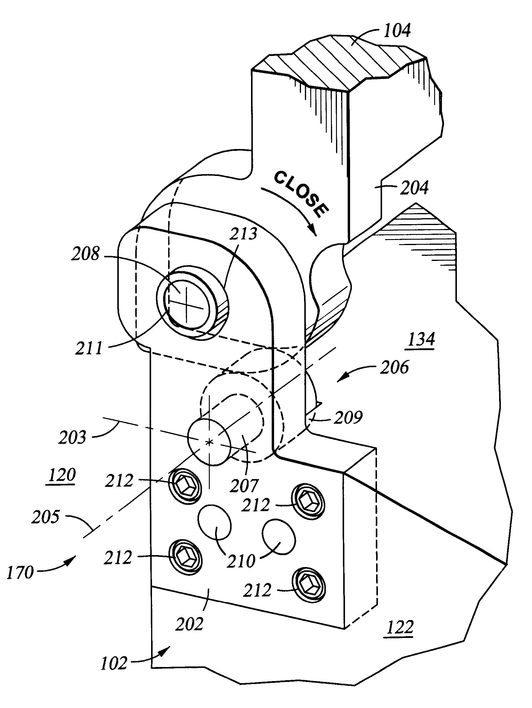
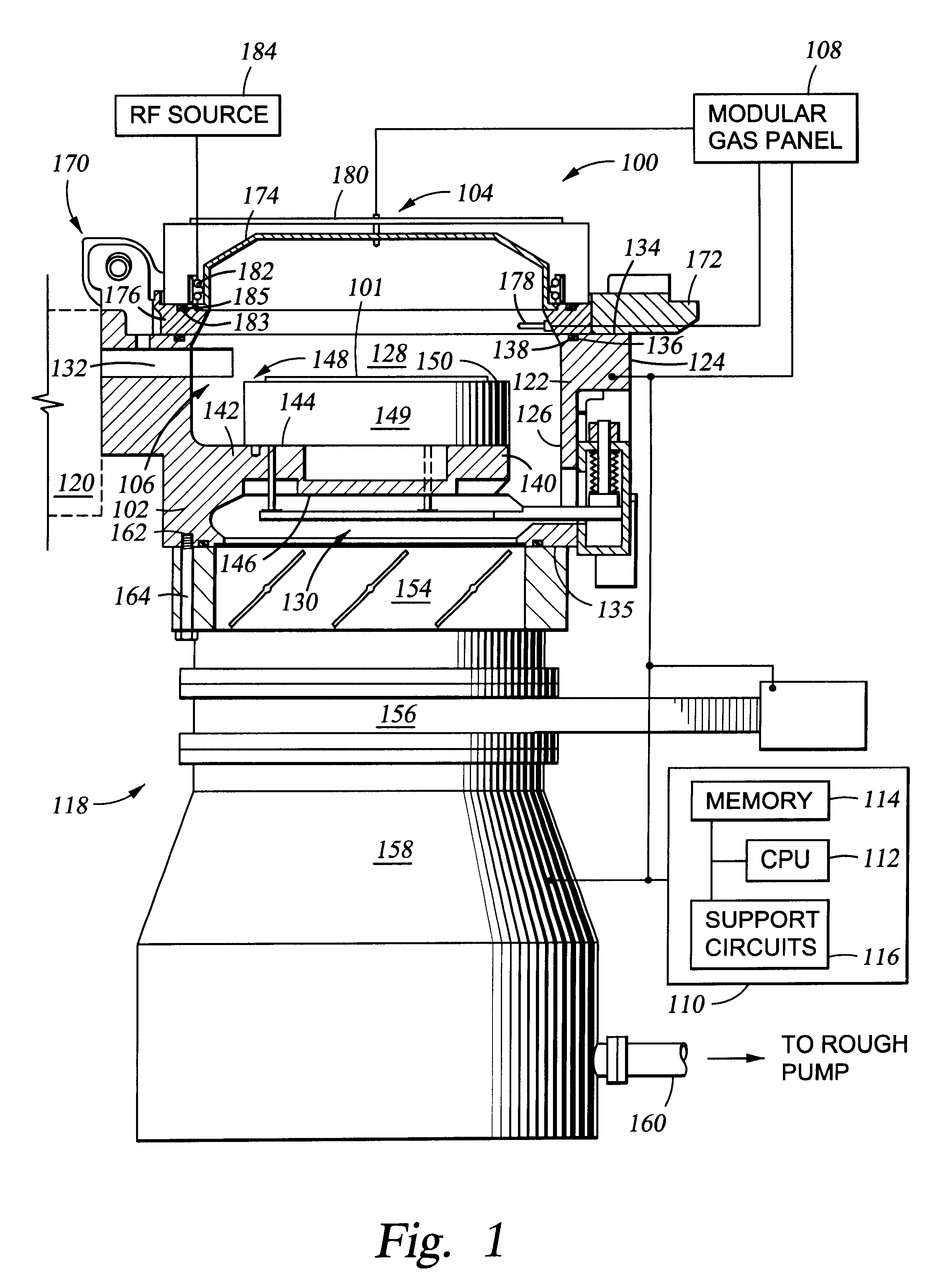
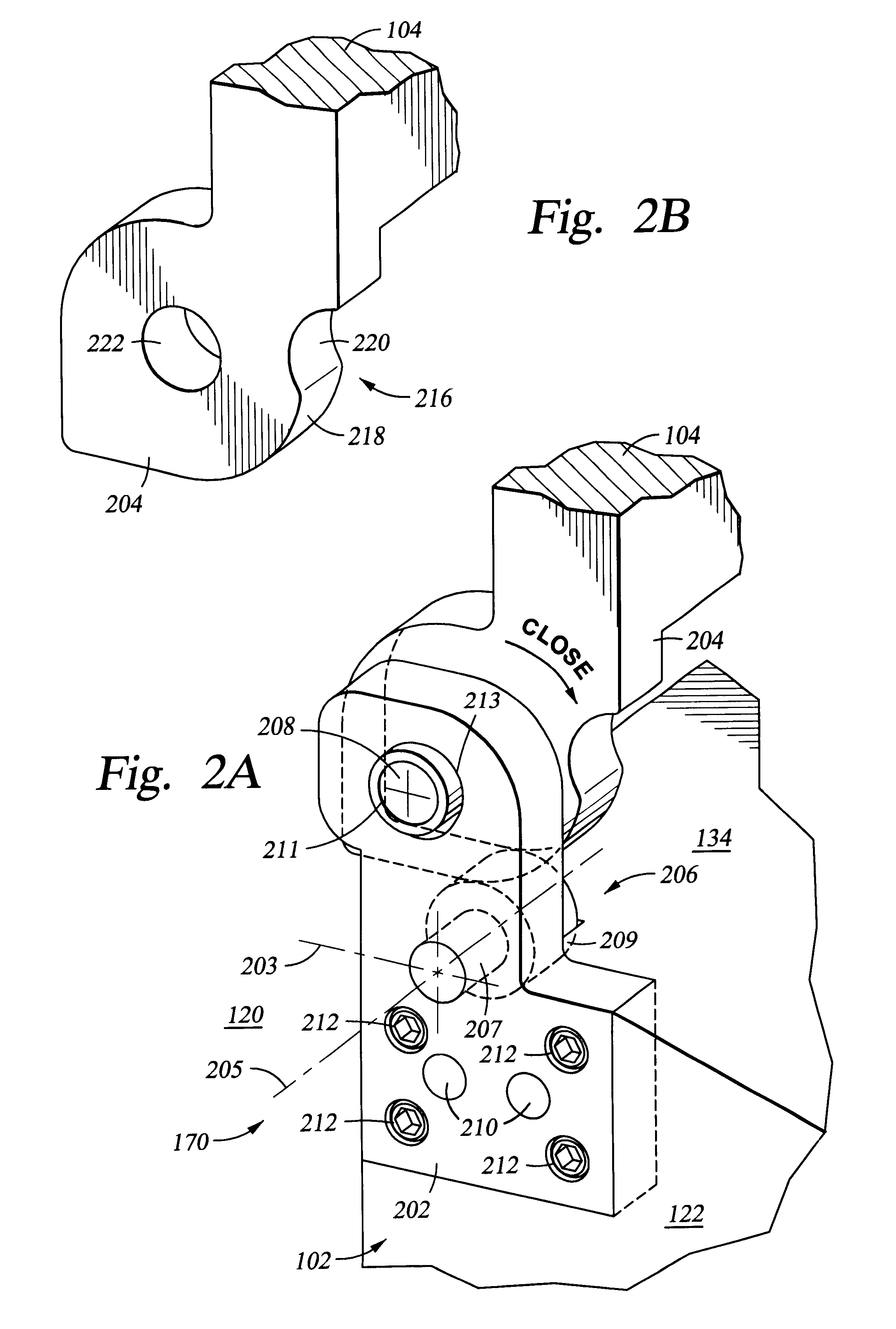
The disadvantages associated with the prior art are overcome by the present invention of semiconductor substrate processing system. The semiconductor processing system generally comprises a chamber body that has a semiconductor substrate support assembly disposed in the chamber body. A lid assembly is movably coupled to the chamber body via a dual pivot hinge assembly. The hinge assembly provides two pivot points that minimize the abrasion and pinching of an o-ring disposed between the lid assembly and the chamber body upon closing of the lid assembly.
In a second embodiment of the first hinge assembly, the cam plate extends from the chamber body. Specifically, a hinge block is attached to the chamber body and comprises a contoured edge for interfacing with a cam follower extending from a side of a lid assembly. The contoured edge serves as a cam plate. Furthermore, the hinge block comprises an aperture for receiving a shaft coupled to the lid assembly a distance from the cam follower. The aperture is sized larger than the diameter of the shaft thereby allowing for rotational and translational motion.
Coinciding with the hinge assembly of each of the embodiments is a second hinge assembly is disposed on the other side of the lid assembly allowing the rotation of the lid assembly to be defined by the first hinge assembly. The dual pivot action of the first hinge assembly allows the lid assembly to remain clear of the processing platform using the first inner pivot point defined by the aperture. The second outer pivot point defined by the cam follower seats the lid assembly with a substantially normal motion relative the o-ring, thus minimizing abrasion and "pinching" of the o-ring upon closing the lid assembly.

Problems solved by technology

Integrated circuits have evolved into complex devices that include millions of transistors, capacitors and resistors on a single chip.
One observed problem is degradation in the o-ring that forms the seal.
As such, the o-ring has been subjected to pinching, nicking, and abrasion between the lid and top surface of the chamber.

Method used


Image

  • Chemical vapor deposition chamber lid assembly
  • Chemical vapor deposition chamber lid assembly
  • Chemical vapor deposition chamber lid assembly

Examples


second embodiment

Other embodiments of the first hinge assembly 170 include various derivations utilizing the dual pivot action of the preferred embodiment depicted in FIGS. 2A, 2B, 5, 6, and 7. FIG. 3 depicts a cross-sectional view of the first hinge assembly 170. Specifically, a hinge block 350 is attached to the chamber body 102 and comprises a contoured edge 352 for interfacing with a cam follower 354 extending from a side 355 of a lid assembly 104. In this manner, the contoured edge 352 serves as a cam plate.

Furthermore, the hinge block 350 comprises an aperture 356 for receiving a shaft 358 coupled to the lid assembly a distance from the cam follower 354. A person skilled in the art will recognize that alternately, the lid assembly 104 may comprise an aperture (not shown) while the hinge block 350 comprises a shaft (not shown) extending into the aperture of the lid assembly 104. Therefore, the relationship between the aperture and shaft are simply reversed. In either of the embodiments, the ape...

third embodiment

FIG. 4 depicts a cross-sectional view of the first hinge assembly 170, in which the cam plate 472 extends from the chamber body. Specifically, a first surface 134 of a chamber body comprises a projection 472 that functions as a cam plate. Additionally, a hinge block 470 is attached to the chamber body 102 and comprises an aperture 476 for receiving a shaft 478 coupled to a lid assembly 104. The aperture 476 is sized larger than the shaft 478 thereby allowing for rotational and translational motion. The lid assembly 104 further comprises a depression 474 (i.e., contoured surface area) on a lower surface area 468 of the lid assembly 104. The depression 474 interfaces with the cam plate 472 and thereby functions as a cam follower. The cam plate 472 is spaced at a predetermined distance from the shaft 478 of the lid assembly 104. Thus, in a similar manner as described in FIG. 3, in the fully closed position, the lid assembly 104 closes substantially parallel to the first surface 134 of ...


PUM

PropertyMeasurementUnit
diametersaaaaaaaaaa
diameteraaaaaaaaaa
semiconductoraaaaaaaaaa

Abstract

A semiconductor substrate processing chamber is disclosed generally comprising a chamber body that has a semiconductor substrate support assembly disposed in the chamber body. A lid assembly is movably coupled to the chamber body via a dual pivot hinge assembly. The hinge assembly provides two pivot points that minimize the abrasion and pinching of an o-ring disposed between the lid assembly and the chamber body upon closing of the lid assembly.

Description

BACKGROUND OF THE DISCLOSURE1. Field of InventionThe present invention relates generally to apparatus for processing semiconductor wafers. More specifically, the invention relates to a lid assembly of a process chamber used for depositing material on a semiconductor wafer during a chemical vapor deposition process.2. Description of the Background ArtIntegrated circuits have evolved into complex devices that include millions of transistors, capacitors and resistors on a single chip. The evolution of chip designs continually requires faster circuitry and greater circuit density. As the demand for integrated circuits continues to rise, chip manufactures have demanded semiconductor process tooling having increased wafer throughput and greater product yield. To meet this increase in throughput, tooling is being developed to process wider diameter wafers, for example, wafers having diameters of 300 millimeters (mm).Processing chambers generally capable of processing 300 mm diameter wafers...

Claims


Application Information

Patent Timeline
Patent Type & Authority Patents(United States)
IPC IPC(8): C23C16/44
CPCC23C16/44Y10T16/53238Y10T16/532Y10T16/5323
Inventor PANG, LILY L.CHO, THOMAS K.ISHIKAWA
Owner APPLIED MATERIALS INC
Why Eureka
Try Eureka