
Video signal converting apparatus

a technology of video signal and converting apparatus, which is applied in the direction of signal generator with optical-mechanical scanning, picture reproducers using projection devices, and television systems. it can solve the problems of difficult to prevent rapid degradation of the reproduced image, take a long time to create the video signal, and long time to make discriminating processing

Inactive Publication Date: 2003-01-21
PIONEER CORP
View PDF5 Cites 30 Cited by
  • Summary
  • Abstract
  • Description
  • Claims
  • Application Information

AI Technical Summary

Benefits of technology

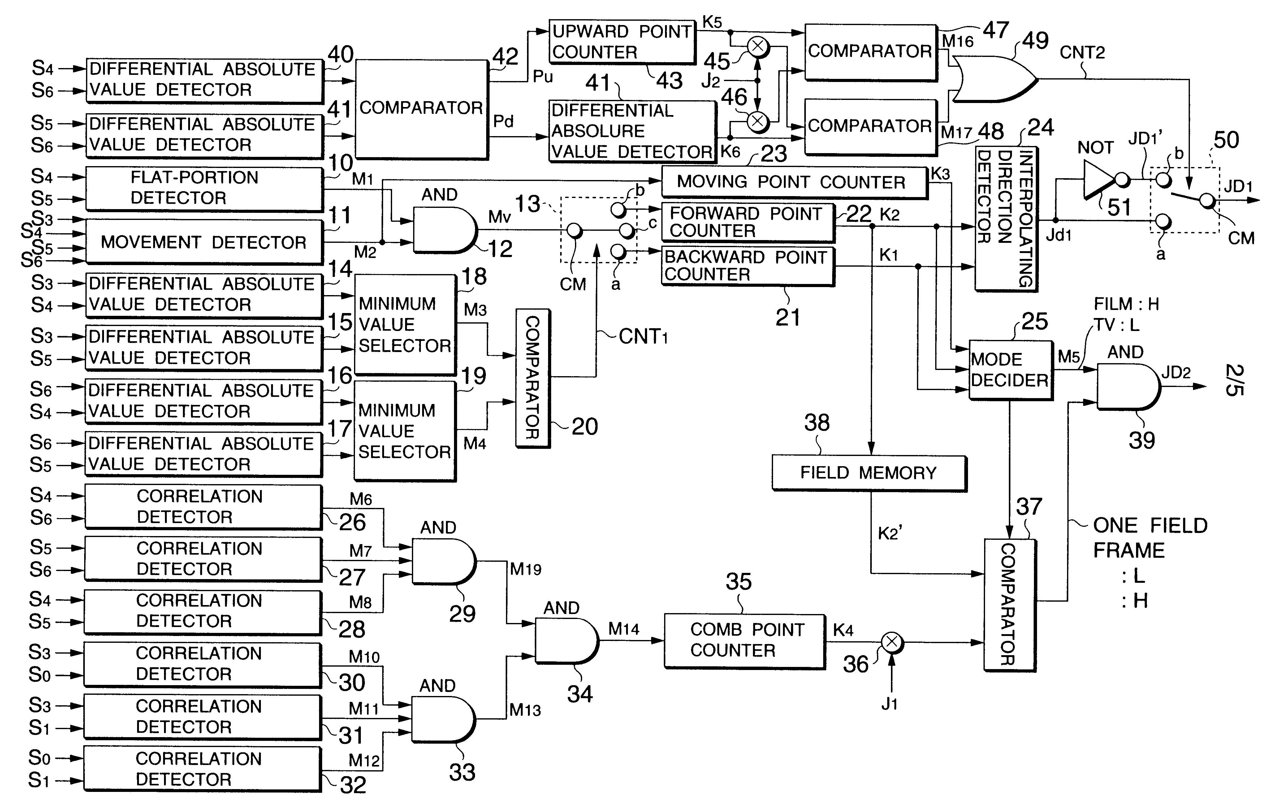
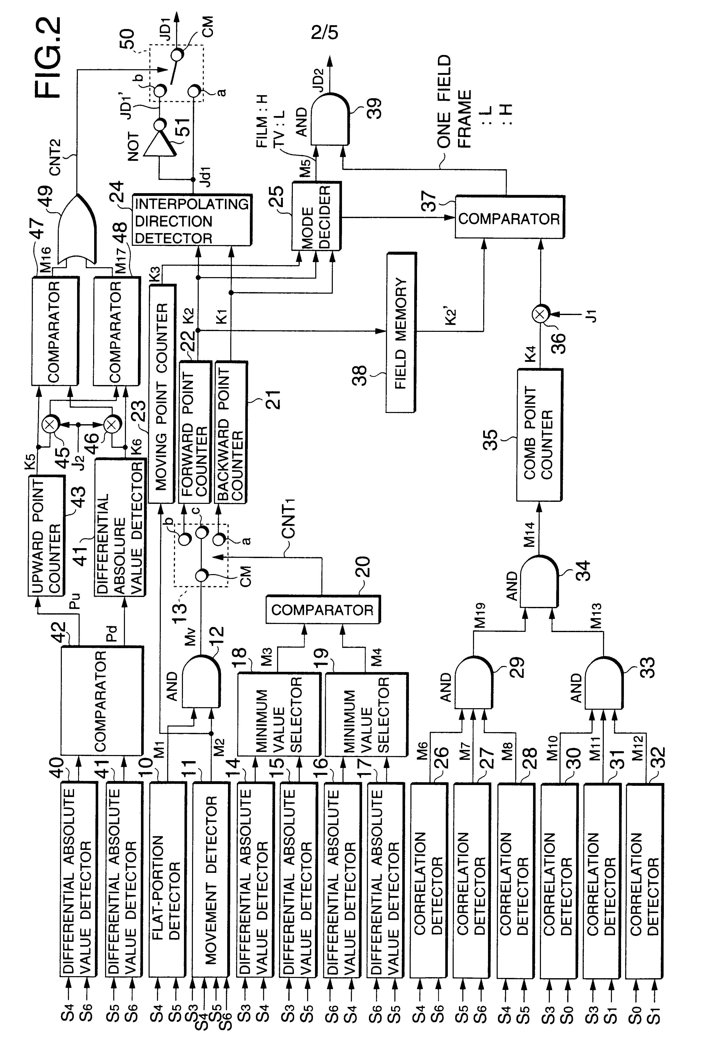
In such a configuration, the telecine-converted video signal of a succession of film frames each having tow fields or more can be detected quickly and surely, and the editing field of the film frame of one field is subjected to suitable interpolating processing. For this reason, the display quality of the video signal by the sequential scanning can be improved which is created from the video signal by the interlaced scanning telecine-converted by the interpolating processing.
In such a configuration, the telecine-converted video signal of a succession of film frames each having tow fields or more can be detected quickly and surely, and the case where there is a movement of one dot or so per one field in the vertical scanning direction is subjected to suitable interpolating processing. For this reason, the display quality of the video signal by the sequential scanning can be improved which is created from the video signal by the interlaced scanning telecine-converted by the interpolating processing.

Problems solved by technology

However, in the above conventional discriminating method, the video signal in the standard television system cannot be quickly discriminated from the telecine-converted video signal so that it takes a long time to create the video signal by the sequential scanning from the video signal in the interlaced scanning.
Therefore, it lakes a long time to make the discriminating processing.
For example, it was difficult to prevent quickly degradation of the reproduced image by, for example, quickly detecting the switching point between the telecine-converted video signal and the ordinary video signal, or quickly detecting a change in the editing point of the video signal once edited.
There was also a problem that the discriminating method must be changed according to the detected periodic pattern.

Method used


Image

  • Video signal converting apparatus
  • Video signal converting apparatus
  • Video signal converting apparatus

Examples


Embodiment Construction

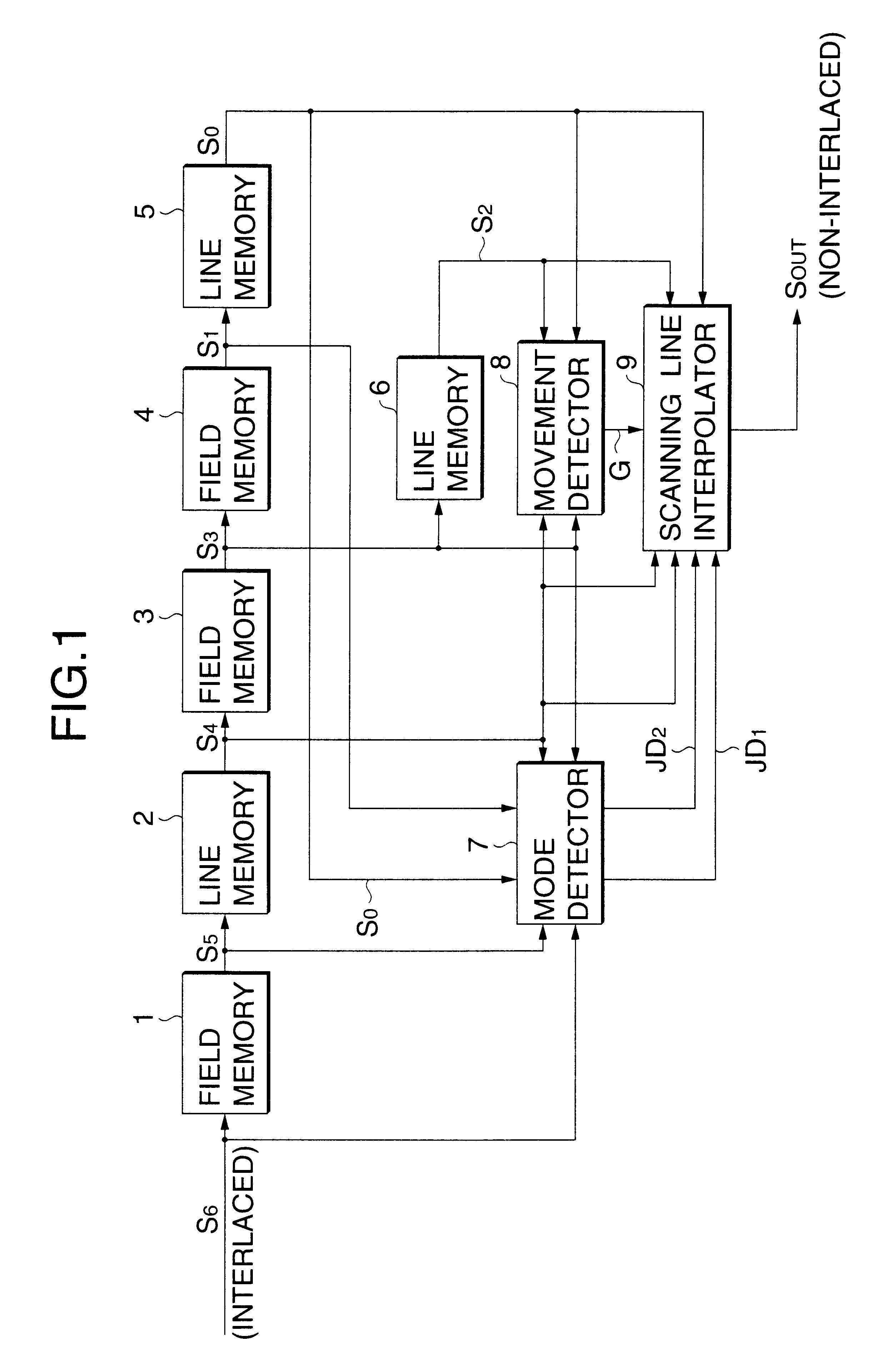
Referring to the drawings, an explanation will be given of an embodiment of the invention. FIG. 1 is a block diagram of a circuit configuration of the video signal converting apparatus according to the embodiment of the invention.

As seen from FIG. 1, in the video signal converting apparatus, an interpolated scanning signal is created from an actual scanning signal of an input video signal by interlaced scanning, and the interpolated scanning signal and the actual scanning signal of the input video signal are interposed between each other, thereby creating the video signal by the sequential (non-interlaced) scanning. The video signal converting apparatus as shown in FIG. 1 can also be applied to e.g. a plasma display panel (PDP).

Where a color video signal is to be processed, two or more video signal converting apparatuses as shown in FIG. 1 are arranged so as to correspond to e.g. luminance signal and a color signal.

As seen from FIG. 1, the video signal converting apparatus includes ...


PUM


Abstract

Whether or not an input video signal is an video signal telecine-converted is decided on the basis of correlation values between an interpolated field and fields located one-field-period before and after the interpolated field. Where the interpolated field is an editing point field of a film frame of one field, adaptive interpolating processing is executed instead of film interpolating processing.

Description

1. Field of the InventionThe present invention relates to a video signal converting apparatus for converting a video signal by 40 laced scanning into a video signal by sequential scanning, and more particularly to a video signal converting apparatus for subjecting the video signal by interlaced scanning to scanning line converting processing suited to the case where it is a telecine-converted video signal created from the screening film by the 2-3 pulldown system.2. Description of the Related ArtA video signal conversion technique is well known, which converts a video signal from a screening film into a video signal in a standard television system such as an NTSC system, and reproduces the converted video signal as well as a video signal in an ordinary television system.In the screening film, a spatial image is sampled as 24 frames per second, whereas in the NTSC system, the spatial image is sampled as 30 frames per second (60 fields per second). Since both adopt different sampling ...

Claims


Application Information

Patent Timeline
IPC IPC(8): H04N7/01H04N5/44H04N5/46
CPCH04N7/0112H04N7/0137H04N7/012H04N5/46Y10S348/911
Inventor HONDA, HIROFUMI
Owner PIONEER CORP
Learn More