Intake air control system of engine
a technology of control system and intake air, which is applied in the direction of electrical control, ignition automatic control, non-mechanical valves, etc., can solve the problems of difficult to control the intake air amount to a desired value, certain pumping loss of the engine, and larger engine torque lowering
- Summary
- Abstract
- Description
- Claims
- Application Information
AI Technical Summary
Problems solved by technology
Method used
Image
Examples
first embodiment
Referring to FIG. 3, there is shown a flowchart of operation steps adopted in the present invention.
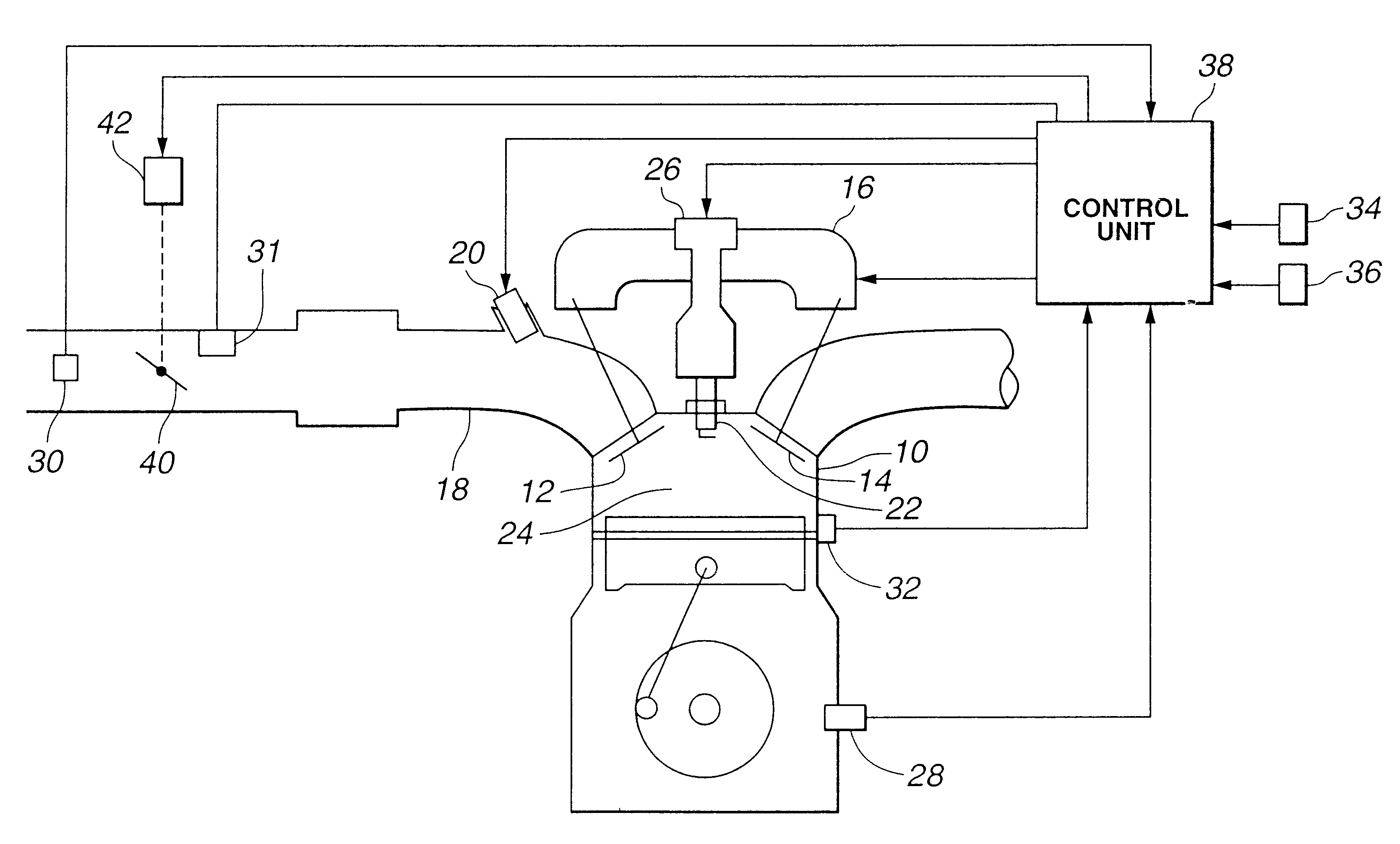
At step S1, based on the accelerator open degree (APO) and the engine speed (Ne), a target intake air amount (Q) needed for obtaining a target engine torque is calculated. In this step, the target intake air amount (Q) is directed to the amount needed by the first control mode wherein the intake air amount is controlled mainly by controlling the open / close timing of the variable valve. Specifically, the target intake air amount (Q) is derived by looking up a map of FIG. 4 that shows a relation between the accelerator open degree (APO), the engine speed (Ne) and the target intake air amount (Q).
Preferably, the target intake air amount (Q) is an amount that is derived by adding an intake air amount needed for idling the engine 10 to the above-described target intake air amount (Q).
At step S2, one of the first and second control modes is selected in accordance with an operation condition...
second embodiment
Referring to FIG. 6, there is shown a flowchart of operation steps adopted in the present invention.
Since steps S1, S2, S3 and S4 are the same as those of the above-mentioned first embodiment, description of them will be omitted from the following.
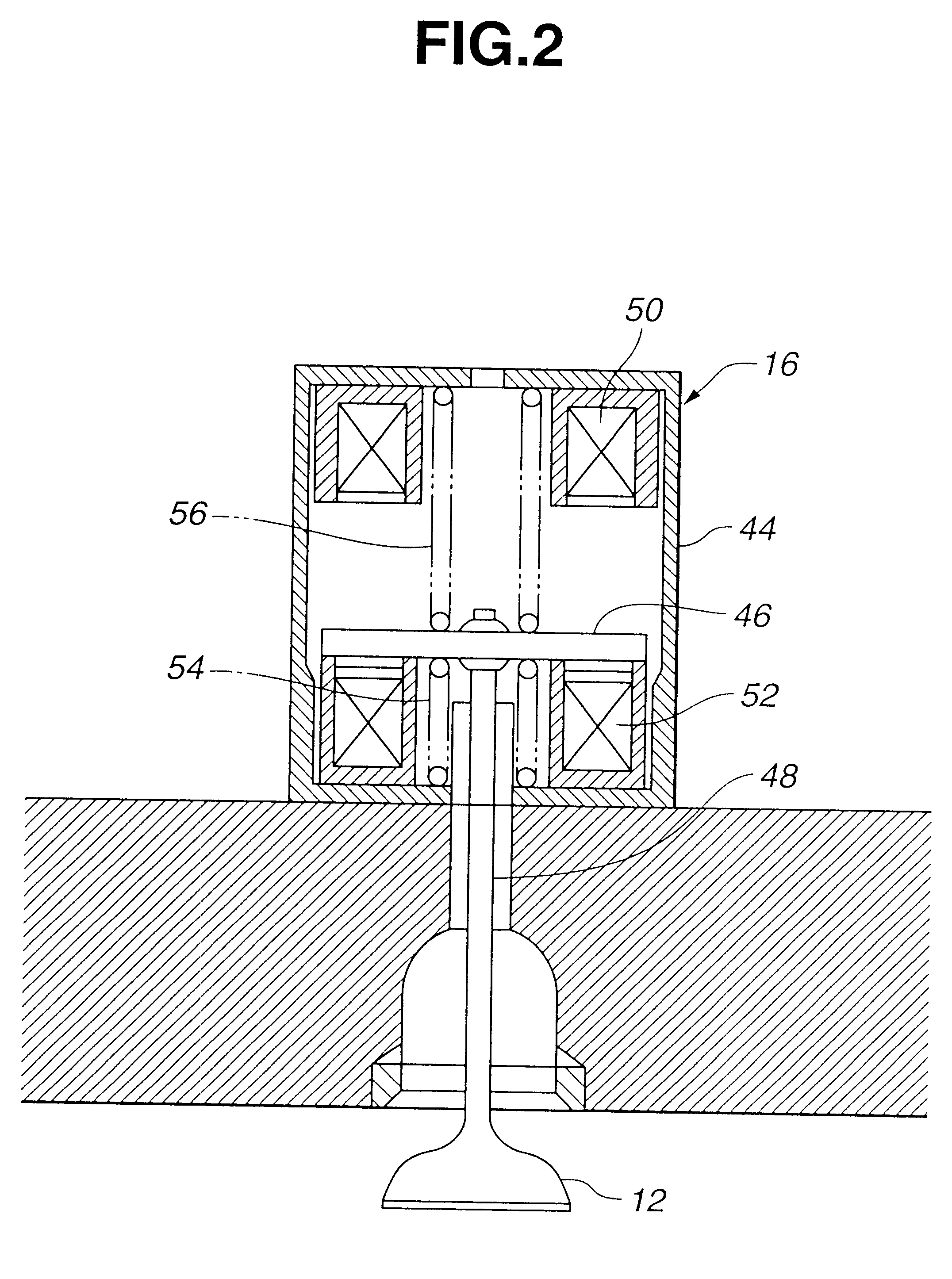
If, at step S2, the second control mode is selected, the operation flow goes to step S11. At this step, a target open / close timing of the intake / exhaust valve 12 or 14 is calculated in such a manner that the target intake air amount (Q) derived at step S1 is obtained by the second control mode, and then the open / close timing thus calculated is actually outputted to the electromagnetic valve actuator 16. Then, at step S12, a thermal efficiency loss compensation correction value "x" is calculated like in the manner taken at step S5 of the above-mentioned first embodiment of FIG. 3. Then, at step S13, a corrected target intake air amount (Q') is obtained by multiplying "Q" and "x" together. Then, at step S14, a target open degree of the throt...
third embodiment
Referring to FIG. 7, there is shown a flowchart of operation steps adopted in the present invention.
Since steps S1, S2, S4, S12, S13 and S14 are the same as those of the above-mentioned second embodiment of FIG. 6, explanation of them will be omitted from the following description.
In the third embodiment, upon switching from the first to second control mode and vice versa, a target value of the open / close timing of the variable valve derived after the switching is converged to a value with a delay. That is, at step S3', a delayed target open / close timing of the intake / exhaust valve 12 or 14 is calculated in such a manner that the target intake air amount (Q) is obtained by the first control mode, and the delayed target open / close timing thus calculated is actually outputted to the electromagnetic valve actuator 16. At step S11', a delayed target open / close timing of the intake / exhaust valve 12 or 14 is calculated in such a manner that the target intake air amount (Q) is obtained by ...
PUM
 Abstract
Description
Claims
Application Information
 - R&D
- Intellectual Property
- Life Sciences
- Materials
- Tech Scout
- Unparalleled Data Quality
- Higher Quality Content
- 60% Fewer Hallucinations
Browse by: Latest US Patents, China's latest patents, Technical Efficacy Thesaurus, Application Domain, Technology Topic, Popular Technical Reports.
© 2025 PatSnap. All rights reserved.Legal|Privacy policy|Modern Slavery Act Transparency Statement|Sitemap|About US| Contact US: help@patsnap.com


