
Iron cover

a technology of iron covers and irons, applied in the field of iron covers, can solve the problems of reducing the performance of skis, rubbing typically leaves a non-uniform and discontinuous layer of wax on the surface, and the iron cannot be stowed in a suitcase or a ki

Inactive Publication Date: 2002-12-31
ORIGINALITY
View PDF7 Cites 17 Cited by
  • Summary
  • Abstract
  • Description
  • Claims
  • Application Information

AI Technical Summary

Benefits of technology

The objective of the present invention is to provide a cover for the new ski wax irons used to apply waxes to the bottom of skis, although it can be used with other conventional irons.
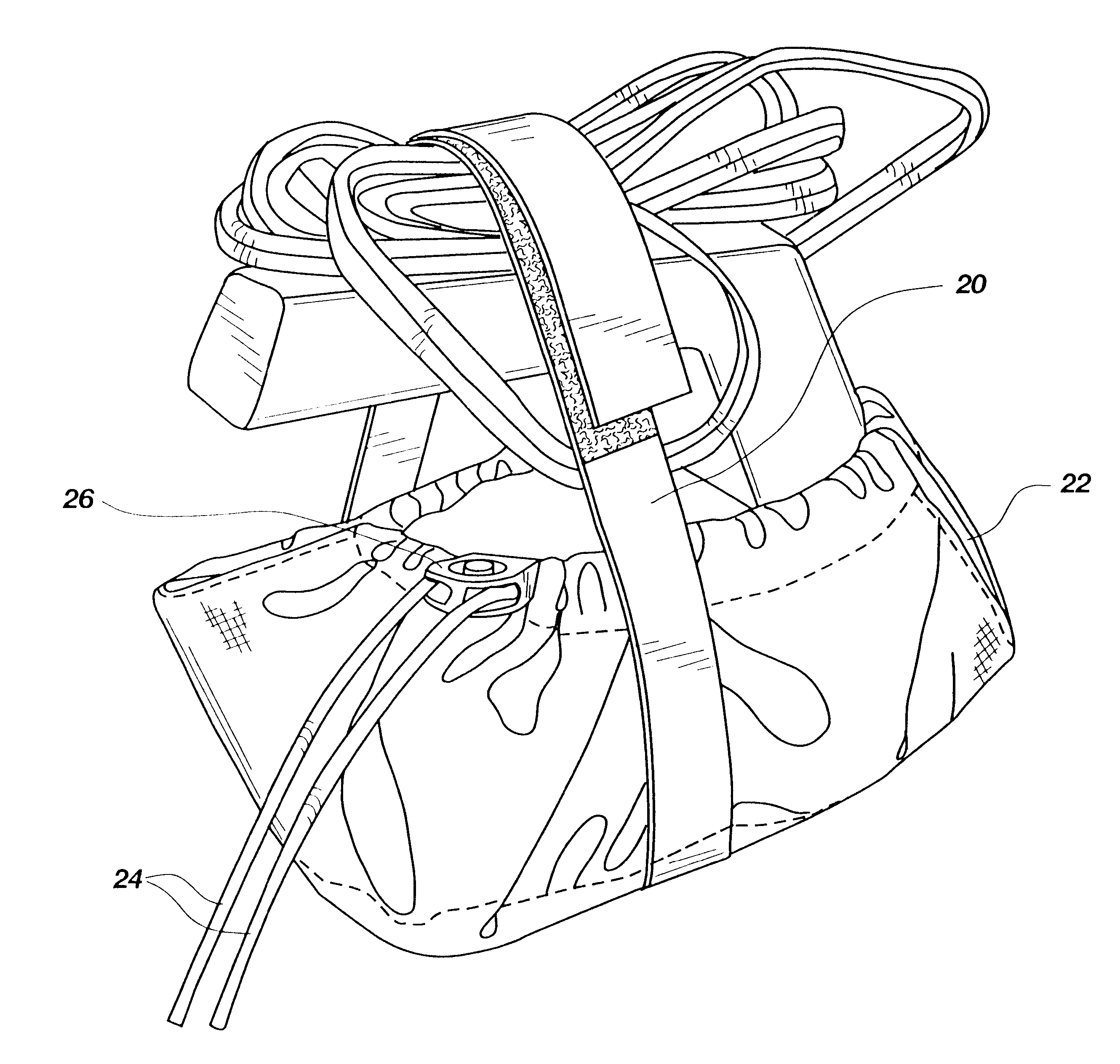
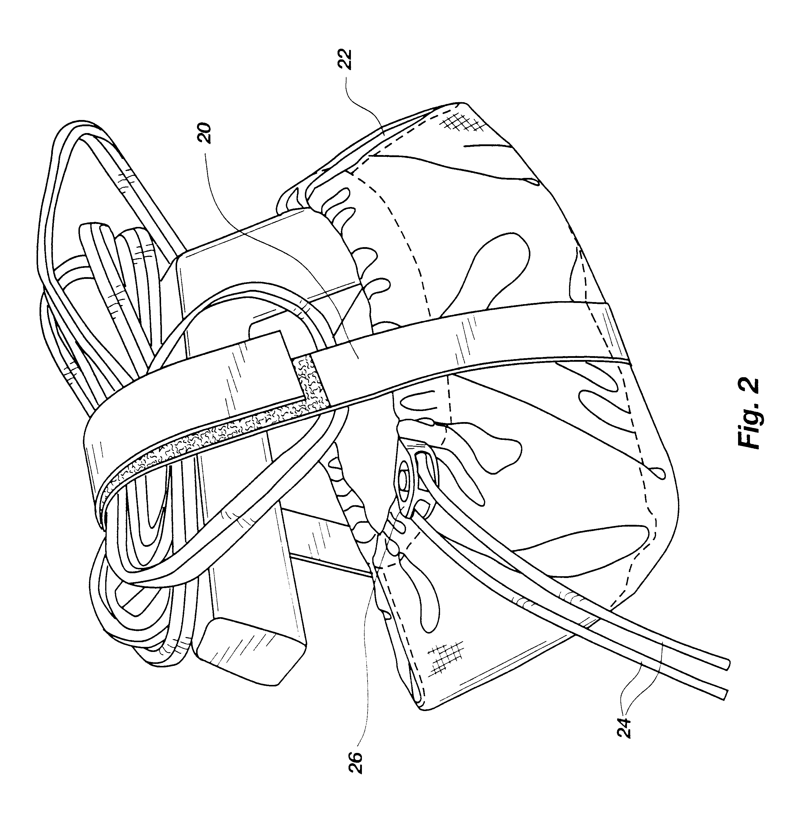
To use the invention, a hot iron is first allowed to cool somewhat so that it won't singe the liner. Then it is placed within the cover on the heat resistant liner segment covering the padded bottom and secured therein with the elastic cord holding the sides flaps. The iron is further secured by the strap system and the iron cord is then folded and secured thereto with the double backed ends of the strap affixed with the corresponding hook and loop strips. Thus stored, the iron cover protects the sole of the iron from scratches and marring. It also prevents direct transmission of the heat from the iron, and allows hot irons to gradually cool during storage. Ski wax irons may therefore be put away in an equipment bag or kit while still warm without damaging waxes and other stored equipment. The power strap storage system also secures the wrapped iron cord and keeps it neatly packed.

Problems solved by technology

These irons cannot simply be stowed in a suitcase or kit where items may be damaged in close proximity to the heated iron.
This hand rubbing typically left a non-uniform and discontinuous layer of wax on the surface, which then had to be smoothed with a piece of plastic or cork.
Thus the bottom of the ski wax iron must be smooth to prevent uneven application of the wax or roughing the sliding surface; thereby reducing the ski's performance.
However, when turned off, they still are too hot to be placed into an equipment bag without damaging other items placed therein, such as supplies of waxes.
This causes water to get into the electronics damaging the iron.

Method used


Image

  • Iron cover
  • Iron cover
  • Iron cover

Examples


Embodiment Construction

As shown in FIG. 1, the invention 10 comprises an iron cover 12 having a square padded bottom 14 formed by a flexible heat resistant reflective liner 16 sewn to a nylon cover 17 shaped to fit over and cover the sole of a ski wax iron. The padded bottom 14 is of sufficient thickness to prevent the sole of the iron from being damaged by accidental contact. Attached to the padded bottom 14 are a plurality of side flaps 18 also covered by the heat resistant liner 16. The side flaps 18 are expandably secured together to extend sufficiently around the sides of the iron placed therein to secure the iron cover there around with draw strings or other securing means. This preferred embodiment uses a reflective nylon heat resistant type of material for the heat resistant liner 16, and a durable nylon for the cover 17.

A strap webbing 20 storage system surrounds and is attached to the bottom 14 to secure the iron and power cord in place. Each side flap 18 is separated and structured when folded ...


PUM


Abstract

An iron cover for ski wax irons a heat resistant liner having a padded bottom segment shaped to cover and protect the sole of an iron and a plurality of side flaps with ends. The side flaps extend sufficiently around the sides of an iron placed within the liner, and are secured around the iron with an elastic cord associated with the side flaps. The side flaps are structured and separated to define a plurality of heat release vents to allow heat to escape from a hot iron placed in the cover for storage.

Description

1. FieldThis invention relates to heating irons. In particular, it relates to heating iron covers for ski wax irons.2. State of the ArtA number of iron covers are known. Iron covers are used for a variety of purposes such as preventing the scorching of materials being ironed. Doyel, U.S. Pat. No. 5,987,788 provides a removable iron cover with steam passage holes made of polytetrafluroethylene (PTFE) inserted over the sole plate of a steam iron to facilitate the efficient delivery of steam from the iron to the material being ironed. It also reduces friction, and acts as a thermal barrier to prevent burning of the material. Emberson-Nash et al, U.S. Pat. No. 5,815,962 provides another attachable cover for the soleplate of a hand steam iron made of a relatively thin sheet of friction reducing PTFE material including steam passage holes which provides a low friction heat shield for hand pressing steam irons.A number of curling iron cases have been designed for storing curling irons that...

Claims


Application Information

Patent Timeline
Patent Type & Authority Patents(United States)
IPC IPC(8): D06F75/38D06F75/00
CPCD06F75/38
Inventor BROWN, ELI
Owner ORIGINALITY
Learn More