
Cyrogenic inertial micro-electro-mechanical system (MEMS) device

a micro-electromechanical system and inertial micro-electromechanical technology, applied in the direction of acceleration measurement using interia forces, instruments, lighting and heating apparatus, etc., can solve the problems of inherent resistance, mems operation presents obstacles, and the method of operation can be affected

Inactive Publication Date: 2002-12-03
HONEYWELL INT INC
View PDF8 Cites 63 Cited by
  • Summary
  • Abstract
  • Description
  • Claims
  • Application Information

AI Technical Summary

Problems solved by technology

Mechanical properties and environmental parameters such as these can largely affect operation of a MEMS device due to a small size and shape of the MEMS device.
Thus, methods of operation can be affected due to inherent electrical and mechanical properties of a MEMS.
MEMS operation presents obstacles due to these challenges present within the micro-machine domain.
For example, a typical electrical conductor, such as gold, includes intrinsic electronic noise, which leads to inherent resistance, which can dominate operation of MEMS.
For example, in operation of vibratory MEMS, such as a MEMS tuning fork gyroscope, the performance of the MEMS may be limited due to physical limitations of materials used within the MEMS, such as electrical conductors.
For instance, Johnson noise (e.g., thermal noise) may be present within electrical conductors.
The Johnson noise power per unit bandwidth is proportional to absolute temperature and is independent of frequency, therefore operation of a MEMS at higher temperatures induces a larger Johnson noise.
In addition, typical operation of a MEMS may be affected due to the Seebeck effect.
In this situation, fluctuations in the temperature can produce voltage noise in MEMS devices.
Brownian motion is a fundamental limitation to the ability to measure the position of a MEMS device.
Consequently, typical operation of a MEMS may be limited by inherent mechanical and electrical properties.
As such, existing MEMS may not be able to meet manufacturing requirements and / or desired applications of MEMS.

Method used


Image

  • Cyrogenic inertial micro-electro-mechanical system (MEMS) device
  • Cyrogenic inertial micro-electro-mechanical system (MEMS) device
  • Cyrogenic inertial micro-electro-mechanical system (MEMS) device

Examples


Embodiment Construction

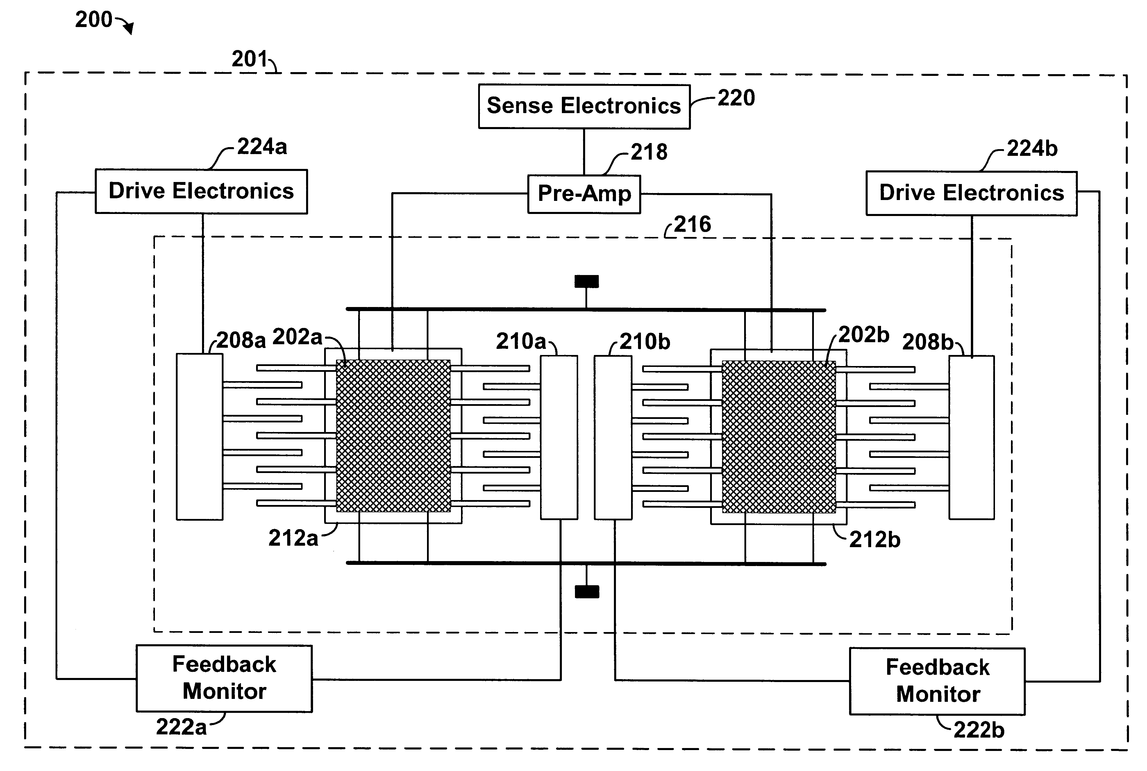
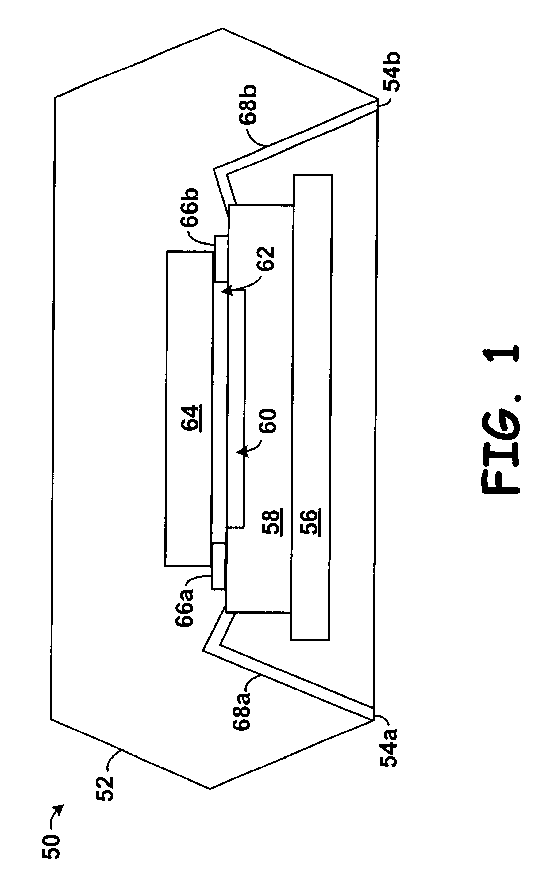
FIG. 1 illustrates one embodiment of a Micro-Electro-Mechanical System (MEMS) 50. While FIG. 1 illustrates MEMS 50, other inertial MEMS devices or sensors may be employed as well. For example, a MEMS gyroscope, which uses a Coriolis acceleration to detect rotation, such as an angular rate-sensing gyroscope, may be used. In addition, it should be understood that the MEMS 50 illustrated in FIG. 1 and other arrangements described herein are set forth for purposes of example only, and other arrangements and elements can be used instead and some elements may be omitted altogether, depending on manufacturing and / or consumer preferences.

By way of example, MEMS 50 has a housing such as a molded plastic package 52 having y multiple electrical contacts 54(a-b). A substrate 56 is present at or near the base of the MEMS 50 within the plastic package 52. A micro-machine chip 58 is coupled to the substrate 56. The micro-machine chip 58 has a micro-machine 60. A cover 64 is coupled to the micro-ma...


PUM


Abstract

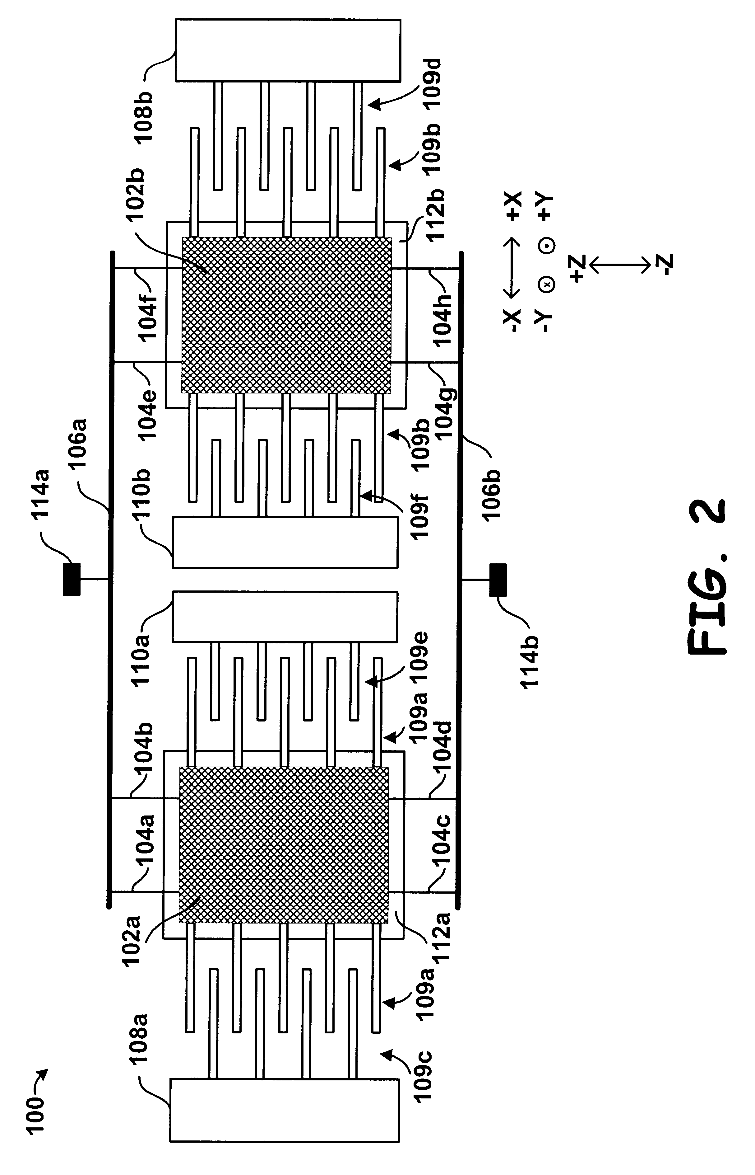
A cryogenic inertial Micro-Electro-Mechanical System (MEMS) device is provided. The device may include a vibratory gyroscope operable to sense a rotational acceleration. The device may also include a pre-amplifier co-located in a close proximity to the vibratory gyroscope. The device may be operated at substantially low temperatures, such as cryogenic temperatures, to reduce electrical noise and improve stability of outputs of the system.

Description

A. Field of InventionThe present invention relates to MEMS devices, and more particularly, to cryogenic inertial MEMS devices.B. Description of Related ArtMicro mechanics, micro-machines, or more commonly, Micro-Electro-Mechanical Systems (MEMS) are an integration of mechanical elements, such as sensors and actuators, and / or electronics on a common substrate through the utilization of micro-fabrication technology. While the electronics are fabricated using Integrated Circuit (IC) process sequences (e.g., CMOS, Bipolar, or BICMOS processes), micro-mechanical components are fabricated using compatible "micro-machining" processes that selectively etch away parts of a silicon wafer or add new structural layers to form mechanical and electromechanical devices.Micro mechanical sensors include a mechanical structure and a sensing device. The mechanical structure is typically deformed and the sensing device transforms the deformation into an electrical signal. The mechanical structure defor...

Claims


Application Information

Patent Timeline
IPC IPC(8): F25B21/02B81B3/00
CPCF25B21/02G01C19/5719F25B2400/15
Inventor PLATT, WILLIAM P.JOHNSON, BURGESS R.
Owner HONEYWELL INT INC
Learn More