
Signal receiving device and radio transmission device and radio transmission method

a technology of receiving device and radio transmission device, which is applied in the direction of program/content distribution protection, selective content distribution, television system, etc., can solve the problems of increasing and complicating the manufacturing process, complicated circuit construction, and large siz

Inactive Publication Date: 2002-11-26
SONY CORP
View PDF3 Cites 12 Cited by
  • Summary
  • Abstract
  • Description
  • Claims
  • Application Information

AI Technical Summary

Benefits of technology

By comparing the code sequence of the transmission data received to the code sequence previously allocated to the receiving side and recognizing the desired transmission data to be received when the comparison result shows identity, the recognizing can be conducted certainly and quickly by the simple processing just to compare and simultaneously, when identity is showed, the control based on the information data of the transmission data can be executed.
Each electronic device transmits the transmission data that is information data to be transmitted having the code sequence of the fixed bit length, formed based on the prescribed identification data, added, to a plurality of electronic devices, compares the code sequence extracted from the data received through the signal receiving means to the code sequence previously allocated to the receiving side, and when the comparison result shows identity, recognizes that the received data is the transmission data transmitted from any one of the plurality of electronic devices, so that recognizing can be conducted certainly and quickly by the simple processing just to compare and control based on the information data of the transmission data can be conducted only when identity is showed.
Each of the plurality of electronic devices transmits the transmission data that is information data to be transmitted having the code sequence of the fixed bit length, formed based on the prescribed identification data, added, to the plurality of electronic devices, compares the code sequence extracted from the data received through the signal receiving means to the code sequence previously allocated to the receiving side, and recognizes that the received data is the transmission data transmitted from any one of the plurality of electronic devices when the comparison result shows identity, so that recognition can be conducted certainly and quickly with the simple processing just to compare and only when identity is showed, control based on the information data of the transmission data can be executed.

Problems solved by technology

However, in the radio network system thus constructed, in the case of conducting recognizing, the complicated arithmetic operation should be conducted with the decipher algorithm, and it caused the problem that the circuit construction became complicated and large in size.
Furthermore, export controls are imposed on the encryption itself and in the case of producing products considering its expansion on the world market, it is difficult to adopt the common encryption standards in the whole world.
And since it is sufficiently considered that each country should adopt its own encryption standard, the encryption standards should be changed depending on the country at the manufacturing stage and thus, it caused the problem in increasing and complicating the manufacturing process.
Furthermore, in a state where the radio network system is constructed in the house and an identical radio network system is constructed in the neighboring house, it has the possibility of interference between these systems and of tapping when interference occurs and thus, it caused the infringement of privacy.

Method used


Image

  • Signal receiving device and radio transmission device and radio transmission method
  • Signal receiving device and radio transmission device and radio transmission method
  • Signal receiving device and radio transmission device and radio transmission method

Examples


Embodiment Construction

Preferred embodiments of this invention will be described with reference to the accompanying drawings:

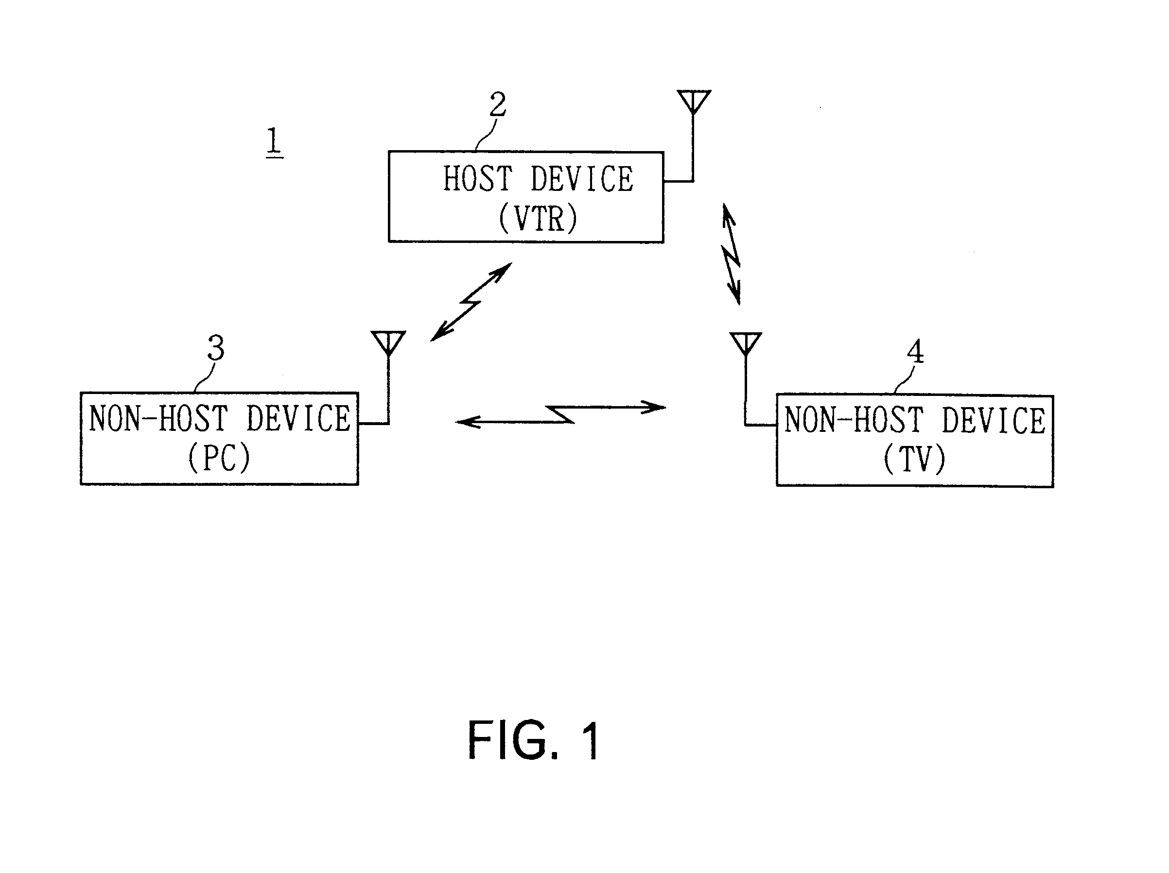
In FIG. 1, 1 generally shows a radio transmission system according to the present invention. A VTR for mainly receiving transmission data is provided as the host device and a personal computer and a TV are set as the non-host devices 3 and 4. These non-host devices 3 and 4 are placed at the optional positions each being a fixed distance from the host device 2 and the non-host devices equipped with transceivers (not shown in FIG. 1) can transmit data by radio to the host device 2 equipped with the similar transceiver (not shown in FIG. 1) using their transceivers.

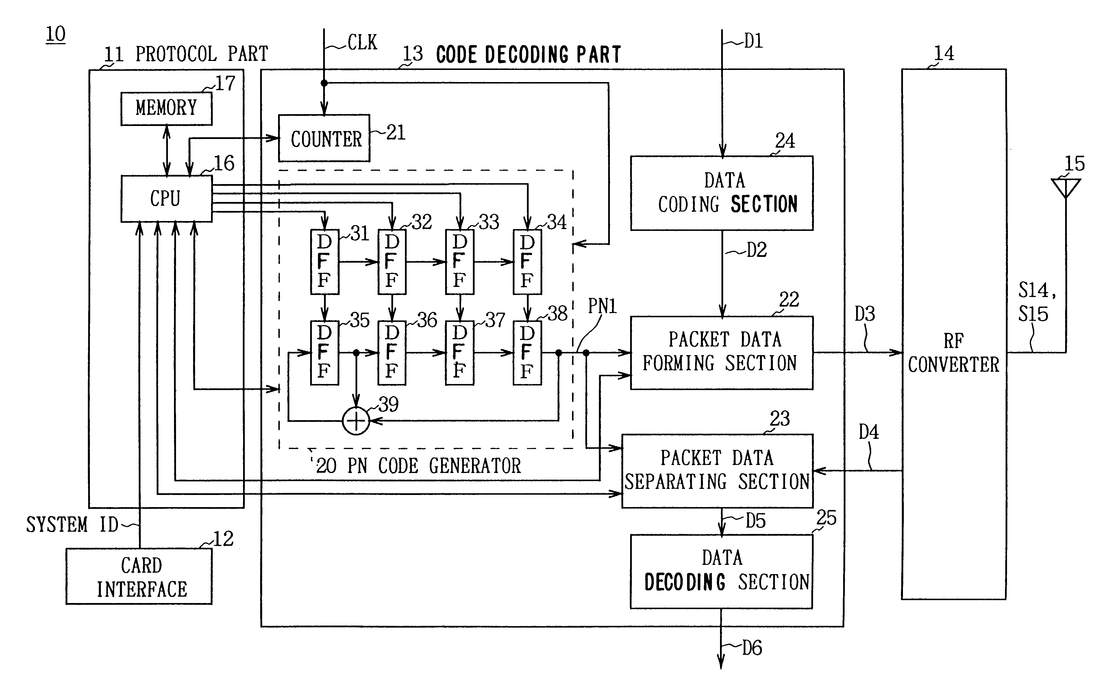
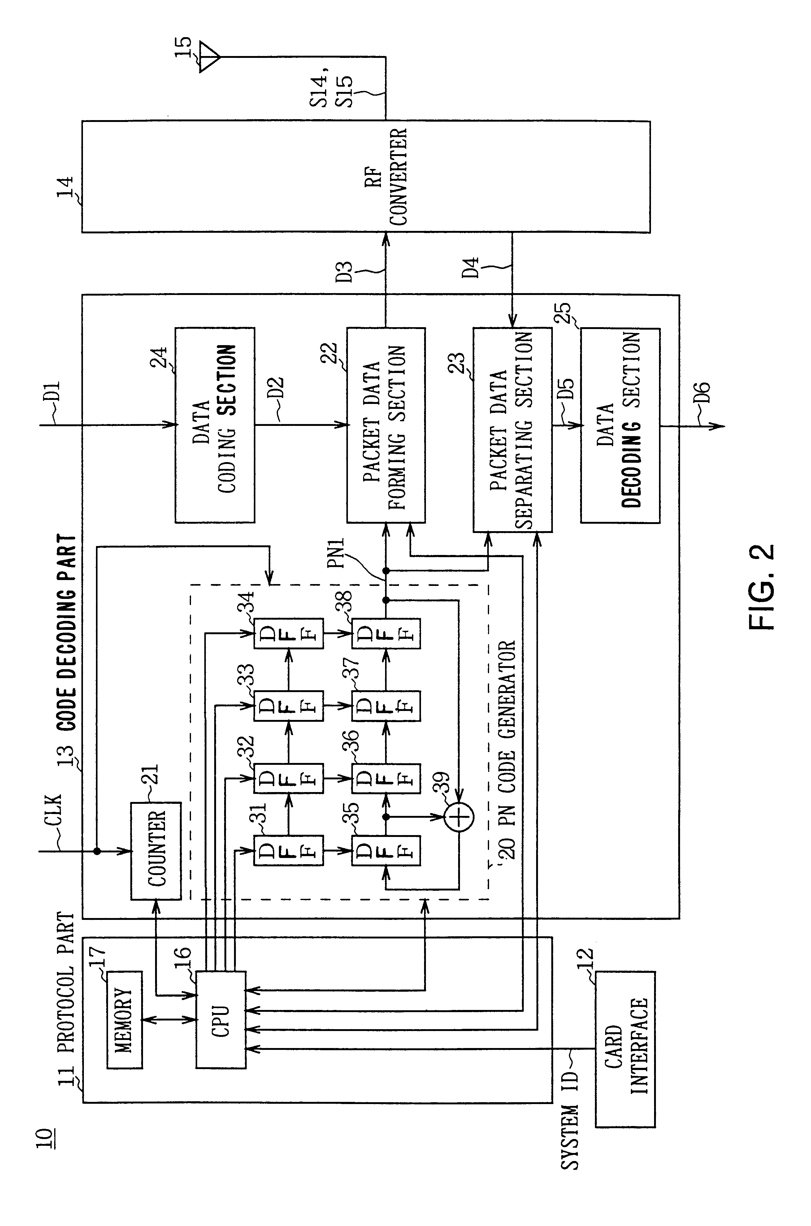
Then, the circuit configuration of the transceivers provided in the host device 2, non-host devices 3 and 4 respectively will be described. In this case, since these transceivers are identical, only the transceiver mounted in the host device 2 will be described and other transceivers mounted in the non-host devices 3 and 4 w...


PUM


Abstract

A signal receiving device, and a radio transmission device and radio transmission method utilized a code sequence extracting circuit for receiving transmission data that is information data to be transmitted having a code sequence of a fixed bit length, formed based on prescribed identification data, and for extracting the code sequence from said transmission data received, a comparison circuits for comparing the code sequence previously allocated to the receiving side with the code sequence of the transmission data extracted by the code sequence extracting circuit, and a control unit for conducting control based on the information data of the transmission data when the comparison result of said comparison circuit shows identity.

Description

1. Field of the InventionThis present invention relates to a signal receiving device, and a radio transmission device and a radio transmission method, and more particularly, is suitably applied to the radio network system that realizes data communications between electronic devices which are connected by radio waves in the house.2. Description of the Related ArtThe radio network system constructing the radio local area network (LAN) system by connecting electronic devices, such as televisions (hereinafter referred to as TV), video tape recorders (hereinafter referred to as VTR) and a personal computer used in a house, has begun to be popular.In such a radio network system, a VTR is set as a host device and a personal computer and TV are set as non-host devices. These non-host devices such as the personal computer and TV are installed at the optional positions each being a fixed distance from the host device VTR, and data can be transmitted by radio to the host device equipped with a...

Claims


Application Information

Patent Timeline
IPC IPC(8): H04B1/707H04N7/18G06F21/10H04B1/16H04L9/16H04L9/20H04N5/00H04N7/167H04N21/4363H04N21/442
CPCH04B1/70735
Inventor KAMO, TAKANOBU
Owner SONY CORP
Learn More