
Delivery unit arranged in a surge chamber of a fuel tank of a motor vehicle

a technology of fuel tank and surge chamber, which is applied in the direction of positive displacement liquid engine, piston pump, charge feed system, etc., can solve the problems of complicated design, complicated configuration of the pump holder, and increased maintenance work of the fuel pump

Inactive Publication Date: 2002-11-12
CONTINENTAL AUTOMOTIVE GMBH
View PDF20 Cites 22 Cited by
  • Summary
  • Abstract
  • Description
  • Claims
  • Application Information

AI Technical Summary

Benefits of technology

The inventive configuration allows the fuel pump to be simply fitted in and removed from the surge chamber separately from the ejector. According to the present invention, maintenance work on the fuel pump is not hindered by the ejector and is therefore very simple. Furthermore, the inventive configuration allows the fuel pump to have a simple construction and accordingly, may be manufactured at favorable cost. A further advantage of the present invention is that the materials are separated into their correct types during the removal of the delivery unit according to the invention because the pump holder, like the ejector and the surge chamber, is generally manufactured from plastic and the fuel pump usually exhibits a housing cap and a housing cover made of metal.
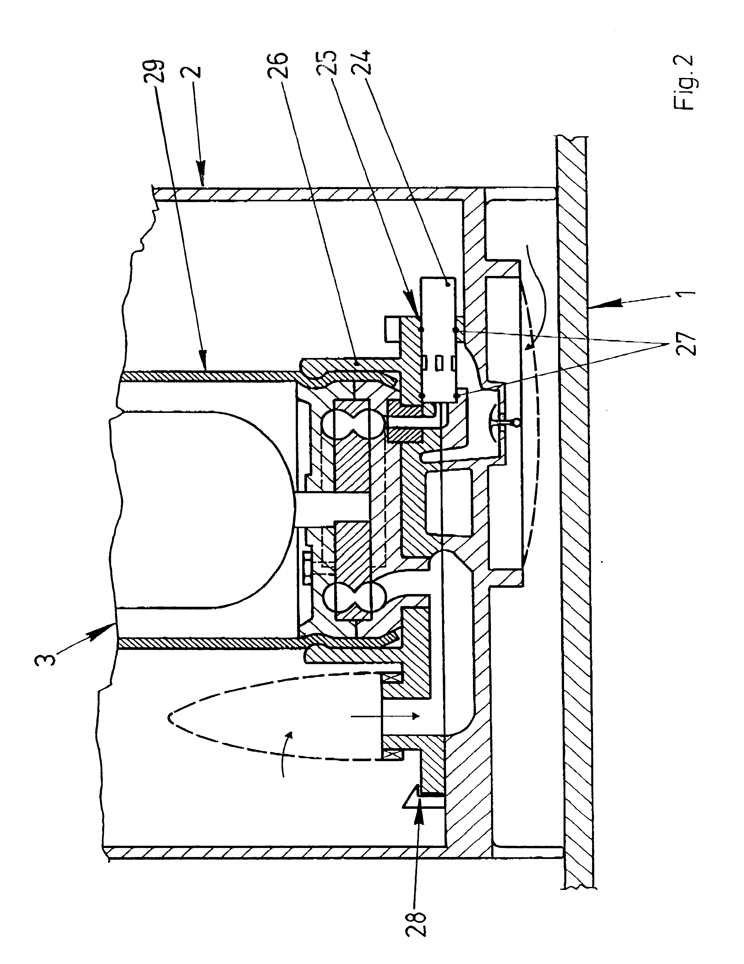
The ejector may be configured in one piece with the pump holder. However, the ejector exhibits a nozzle and a mixing tube at a distance from the nozzle which complicates the configuration of the pump holder. In accordance with another embodiment of the present invention, the pump holder may be particularly easily manufactured if the floor of the surge chamber exhibits a partial region of a mixing tube of the ejector.
In a further advantageous embodiment, the ejector is supplied with fuel via its own pump stage. This additional pump stage may be arranged, in a particularly low-cost manner, in the rotor of the main pump stage in a peripheral pump or side channel pump.

Problems solved by technology

The known fuel pump and ejector combination represents a component of very complex design.
In addition, the ejector makes maintenance work on the fuel pump more difficult.
However, the ejector exhibits a nozzle and a mixing tube at a distance from the nozzle which complicates the configuration of the pump holder.
Because, however, the internal combustion engine of the motor vehicle requires a higher pressure than the ejector, a branch so arranged requires a cost-intensive pressure-reducing valve arranged.

Method used


Image

  • Delivery unit arranged in a surge chamber of a fuel tank of a motor vehicle
  • Delivery unit arranged in a surge chamber of a fuel tank of a motor vehicle
  • Delivery unit arranged in a surge chamber of a fuel tank of a motor vehicle

Examples


Embodiment Construction

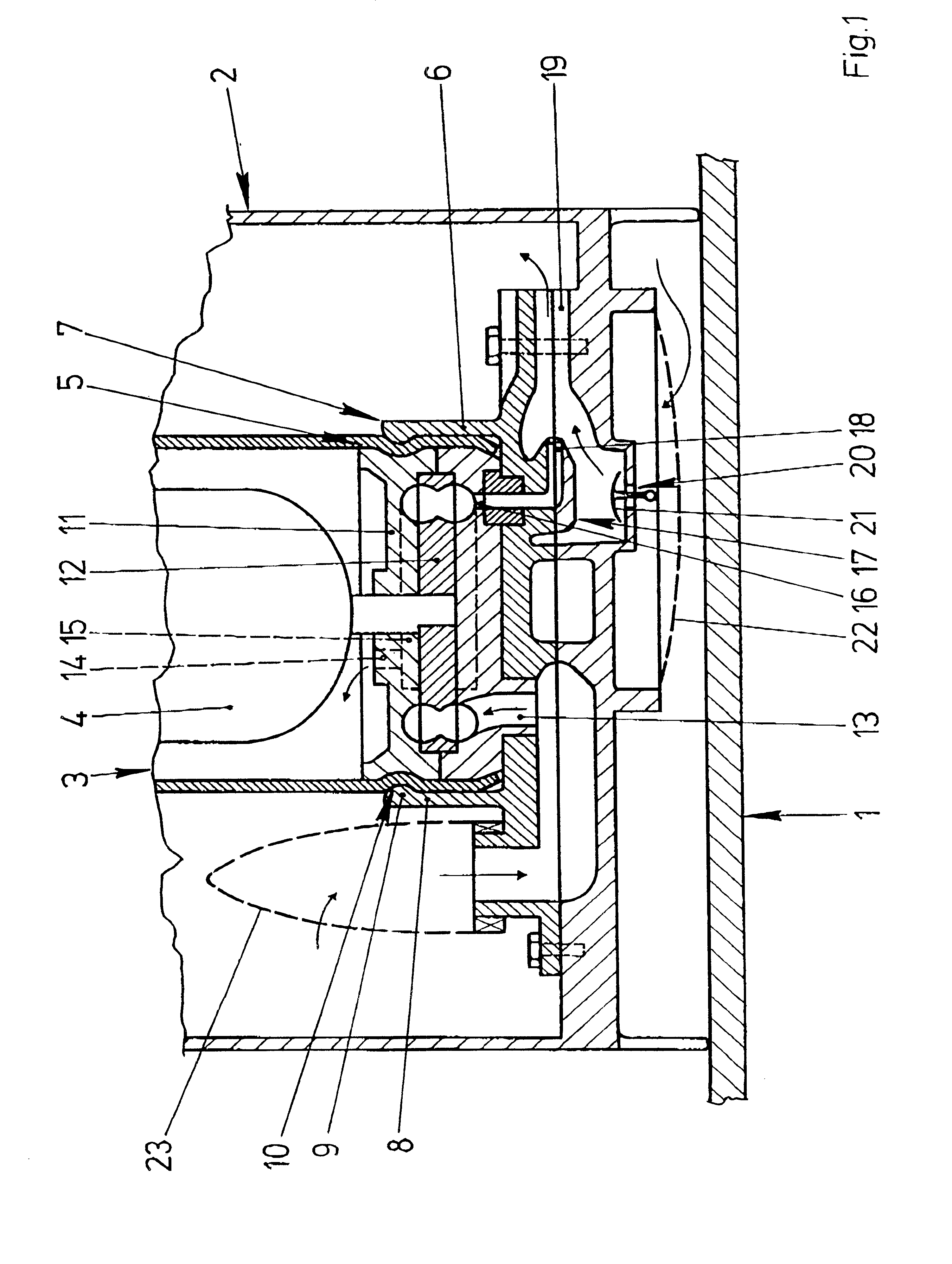
FIG. 1 shows a surge chamber 2 arranged on a floor of a fuel tank 1 of a motor vehicle with a delivery unit 3 arranged in the surge chamber 2. The delivery unit 3 has a fuel pump 5 driven by an electric motor 4 and a pump holder 6 for fastening the fuel pump 5 in the surge chamber 2. The pump holder 6 is screwed to the floor region of the surge chamber 2 and has a snap-in connection 7 to the fuel pump 5. The snap-in connection 7 includes a rim 8 with a protrusion 9 which points radially inwards. The rim 8 stands out from the pump holder 6 and surrounds the fuel pump 5. The protrusion 9 penetrates into a depression 10 in the fuel pump 5 for holding the fuel pump. In FIG. 1, the pump holder 6 is screwed onto the floor region of the surge chamber 2.

The fuel pump 5 is embodied as a side channel pump and has a rotor 12 which rotates in a pump housing 11. The fuel pump 5 further includes a delivery chamber 15 extending from an inlet duct 13 to an outlet duct 14. A branch 16 leads from a c...


PUM


Abstract

A delivery unit arranged in a surge chamber of a fuel tank includes an ejector for filling the surge tank. One half of the ejector is defined by the surge chamber and the other half is defined by a pump holder holding a fuel pump in the surge chamber. The pump holder and the surge chamber are configured as components which are easy to manufacture, thereby allowing the delivery unit to be cost-effectively configured.

Description

1. Field of the InventionThe present invention relates to a delivery unit arranged in a surge chamber of a fuel tank of a motor vehicle having a fuel pump for delivering fuel to an internal combustion engine of the motor vehicle, an ejector connected to the fuel pump for the delivery of fuel from the fuel tank to the surge chamber, and a pump holder for holding the fuel pump in the surge chamber.2. Description of the Related ArtDelivery units having fuel pumps, ejectors, and pump holders are frequently employed in present-day motor vehicles and are known from practice. The pump holder of the known delivery unit has a two-part configuration, a sealing ring inserted in an opening arranged in the floor region of the surge chamber, and an arm fastened to a cap of the surge chamber. The fuel pump is preloaded against the sealing ring by the arm. The ejector is supplied with fuel by the fuel pump and induces the fuel from the fuel tank through an opening. The ejector is integrated in a ho...

Claims


Application Information

Patent Timeline
IPC IPC(8): F02M37/02
CPCF02M37/025
Inventor KOHLHAAS, HELMUT
Owner CONTINENTAL AUTOMOTIVE GMBH
Learn More