
Airship shaped space craft

a spacecraft and airframe technology, applied in the field of airship-shaped spacecraft, can solve the problems of difficult control of spacecraft flight, insufficient airfoil area compared to weight, complex control of spacecraft ascent and descent,

Inactive Publication Date: 2002-10-29
BUNDO MUTSURO
View PDF11 Cites 31 Cited by
  • Summary
  • Abstract
  • Description
  • Claims
  • Application Information

AI Technical Summary

Benefits of technology

Due to the above mentioned structural features, the following advantages can be obtained.
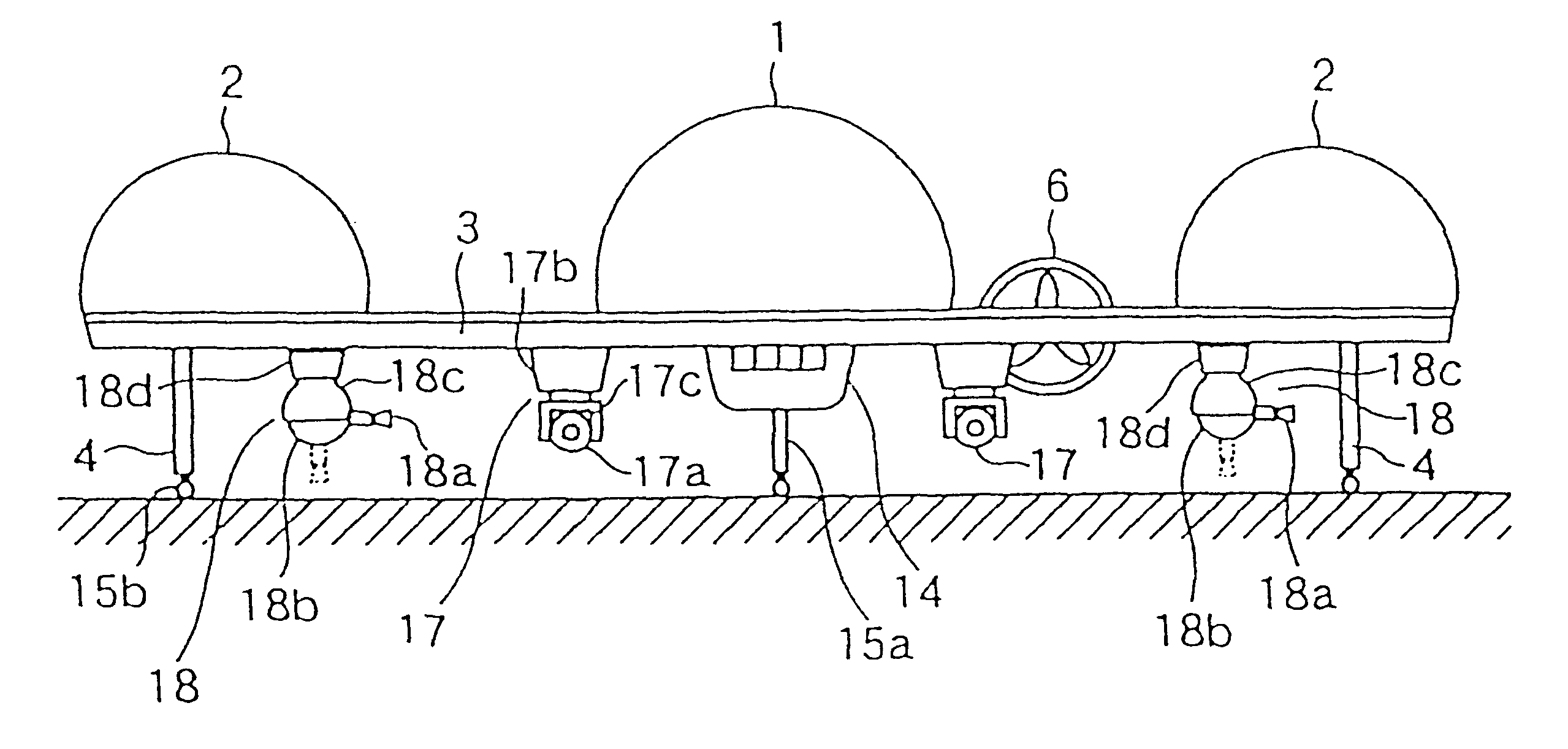
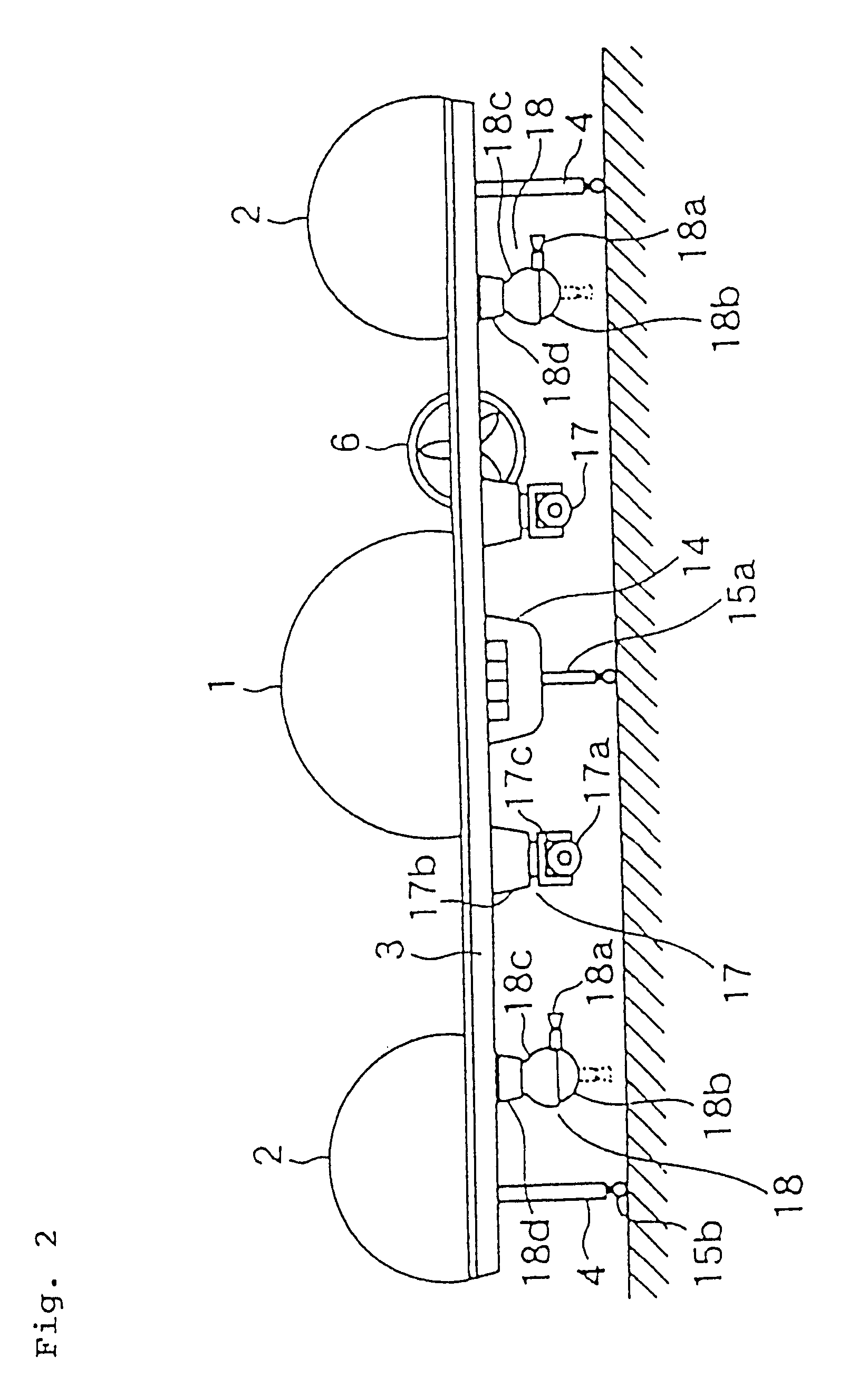
At launch (takeoff) of the space craft of the present invention, at first the direction of each of the propelling devices is made upwards or slantly upwards so as to provide an upward thrust or a thrust having an upward component. By the thrust generated by the propelling devices as above, the buoyancy generated by the gas in the middle fuselage and the outer fuselages, the specific gravity of which is smaller than that of air, and the lift obtained by the horizontal wing, etc., the space craft can safely launch from the ground and thereafter can ascend in the air.
At the return of the space craft according to the present invention, the rocket engines, the jet engines and then the propelling devices are actuated in opposite order with respect to the ascent. At the same time, the amounts and the directions of them are also controlled. By these measures, the descending velocity of the space craft can be sufficiently reduced. Accordingly, aerodynamic heating when the space craft rushes into the atmospheric space is prevented and the space craft can easily be guided with a predetermined velocity and along a predetermined path. Further, at low height, where the propelling devices are used, the operation of the space craft becomes easy, and so it can easily, safely and correctly land on a narrow area of the ground.
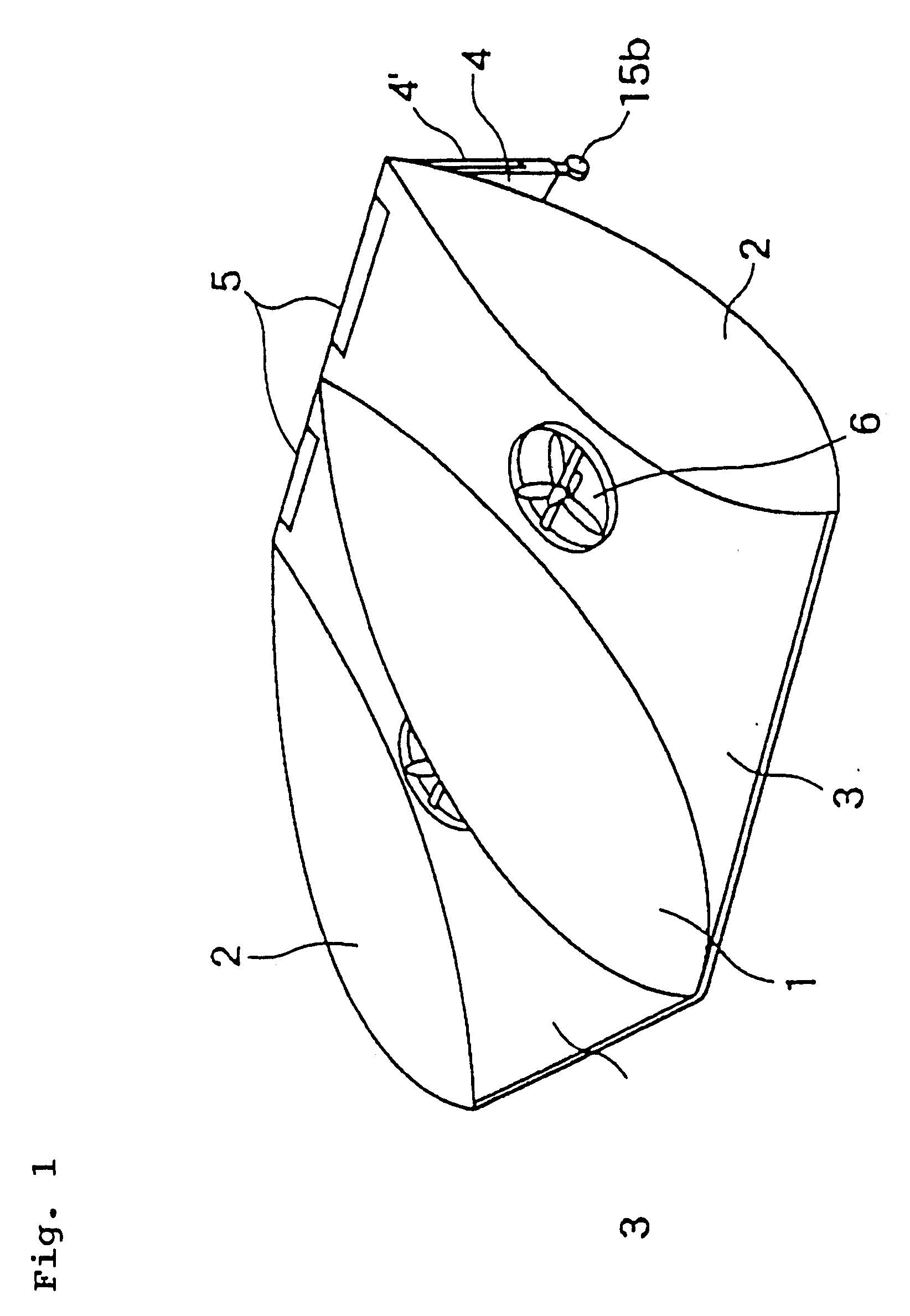
In addition, by the longitudinally half-cut tear-drop shaped and gastight middle and outer fuselages, the flight performance can be improved without an increase in air resistance. By the symmetric arrangement of the propelling devices, the jet engines and the rocket engines on both sides of the middle fuselage, a stable flight can be realized.
Further, as the space craft of the present invention can perform flight as above, it can come back without any damage. Accordingly, it can be repeatedly used, similar to an ordinary airplane.

Problems solved by technology

However, large-scale launching facilities are necessary for both prior types of space craft and control of them during ascent and descent is complex.
Further, both these prior space craft usually have shapes similar to that of an airplane, but their airfoil area cannot be made large enough as compared to their weight.
Accordingly, it becomes difficult to control the flight of the space craft after it rushes into atmospheric space during its return flight, and difficult to land at a predetermined position.
In addition, as the flight velocity when returning to atmospheric space is high, the space craft receives intense aerodynamic heating.
It is thus necessary to adopt a complex structure for the space craft, and it becomes difficult to select appropriate materials for it.
Further, in the prior space craft, it is impossible to use them repeatedly.

Method used


Image

  • Airship shaped space craft
  • Airship shaped space craft
  • Airship shaped space craft

Examples


Embodiment Construction

The present invention will now be described in detail in connection with one preferred embodiment of the present invention illustrated in FIGS. 1 to 7.

Numeral 1 designates a gastight middle fuselage extending in a fore-and-aft direction of the craft body (the usual flight direction) and having a longitudinally half-cut tear drop shape oriented in the fore-and-aft direction. The middle fuselage 1 is connected to a horizontal wing 3, which will be explained later, and constitutes a gas chamber which receives gas, such as helium, with a specific gravity smaller than that of air. Inside of the middle fuselage 1 is provided a skeleton made of an appropriate lightweight and heat-resistant material such as titanium alloy or other superalloy, etc., and an outer shell of the middle fuselage, is also made of an appropriate lightweight and beat-resistant material such as titanium alloy or other superalloy etc. and with a necessary thickness so as to form a gastight construction.

Numerals 2, 2 d...


PUM


Abstract

The present airship-shaped space craft has a middle fuselage extending in a fore-and-aft direction, and a pair of two outer fuselages extending in the fore-and-aft direction located symmetrically on both sides of the middle fuselage. In the above fuselages, gas of a specific gravity of which is smaller than that of air is filled, and the middle fuselage is connected with the outer fuselages by a horizontal wing. The horizontal wing is provided with propelling devices supported in a gimbal fashion for generating thrust in any optional direction, jet engines with backwards directed nozzles to be controlled within a range from a slantwise upward direction to a slantwise downward direction, and rocket engines with ejection nozzles to be controlled in right-and-left and up-and-down directions. During ascent of the space craft, at first the propelling devices, then the jet engines and at last the rocket engines are actuated so as to make the space craft reach and fly along a satellite orbit. Upon return of the space craft, the rocket engines, the jet engines and the propelling devices are actuated in reverse order, and aerodynamic heating at reentry into the atmospheric space can be reduced by making the space craft descend slowly. Also, control of the flight in the atmospheric space becomes easy, so that the space craft can safely and easily land on a predetermined narrow area of the ground.

Description

1. Field of the InventionThe present invention relates to an airship-shaped space craft which can be easily launched without utilizing a complicated construction and large scaled launching facilities, etc., and which can safely return to the ground.2. Description of the Prior ArtIn order to launch prior space craft, such as artificial satellites, which fly in outer space, usually one or a plurality of launching rockets, which are installed on the outside of the craft body, are used. They are burnt successively and then detached from the craft body so as to make the space craft reach a predetermined path around the earth outside of atmospheric space (hereinafter referred to as satellite orbit). In another type of prior art, launching rockets are installed in a space craft with a shape and a construction similar to an aircraft. The space craft can reach satellite orbit by thrust of the launching rockets. The space craft of the latter type is also called a "space plane".However, large-...

Claims


Application Information

Patent Timeline
IPC IPC(8): B64G1/62B64G1/22B64G1/14B64B1/00B64B1/06B64B1/34B64B1/36B64G1/00B64C39/00
CPCB64B1/06B64B1/34B64B1/36B64G1/00B64G1/14B64G1/62
Inventor BUNDO, MUTSURO
Owner BUNDO MUTSURO
Learn More