
Portable visual display device with a collapsible presentation screen

Inactive Publication Date: 2002-10-15
DISPLAYKINETICS
View PDF3 Cites 130 Cited by
  • Summary
  • Abstract
  • Description
  • Claims
  • Application Information

AI Technical Summary

Benefits of technology

It is an object of the present invention that it provides a visual display screen with a viewable surface area that is sufficiently large such that it may be readily and comfortably viewed by several people.
It is a preferable feature of the aforesaid screen assembly and jointing means that they are together configured to avoid or reduce any optical or physical damage or deterioration to the viewable surface of the material of the screen member that may be caused by any position thereof or due to any repeated opening or closing actions.

Problems solved by technology

Visual Display by means of cathode ray tube (CRT) devices is commonly used for computer monitors and televisions and can have relatively large screens (up to 40 inch, 1 meter) but these are bulky and very heavy and thus not truly portable.
Visual display by rear projection such as in TV units can provide a large screen area but such devices are not yet common and again the devices are large and bulky and thus not truly portable.
Visual display devices using a Liquid Crystal Display (LCD) are common particularly in laptop computers and are highly portable but their limited screen size (14 inch, 35 cm) makes them unsuitable for presentational use involving several persons viewing the screen simultaneously in comfort.
Various other displays are appearing such as plasma screens that are large screen (up to 42 inch currently, 105 cm) and that are almost flat for hanging on a wall, but again are relatively heavy and bulky so not truly portable.
This can be a further disadvantage when associated with use where visiting in a business environment since it may be considered professionally "intrusive", to impose these requirements on a client even for informal presentations.
In general these are subject to the limitations either that the viewable screen is smaller than the case within which it is carried, or where the display screen is larger than the case and in some way disassembled for storage and carriage, use of the screen requires user intervention to then assemble the screen and attach it to other required elements which is again an inconvenience and takes time.
However these collapsing methods have not generally proved applicable in translucent diffusion applications for the reasons set out below.
Further, any crease or fold of the material (even if not still physically present or not) may cause optical distortion to the passing light and images or cause "rainbow effect" or "white spots" and result in very irritating screen flaws to a viewer.
As a result, the technology of the screen, its material and also the optical and physical requirements in use are very different from those applicable to reflection screens.
In consequence particular difficulties are encountered in developing collapsible screens of this type, and it has not been generally possible to apply collapsible concepts from the reflection screen art to screens designed for the application of the present invention.

Method used


Image

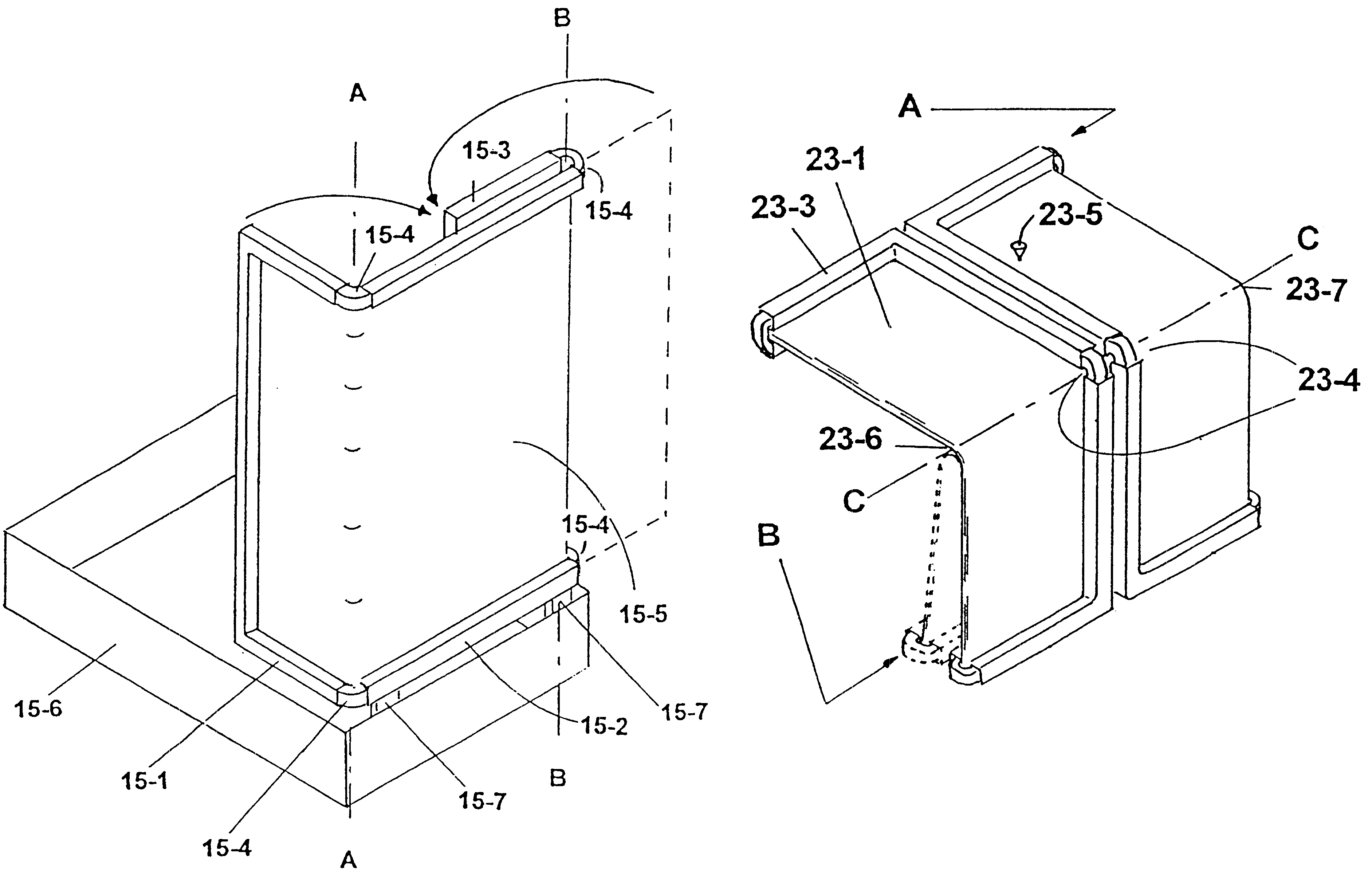
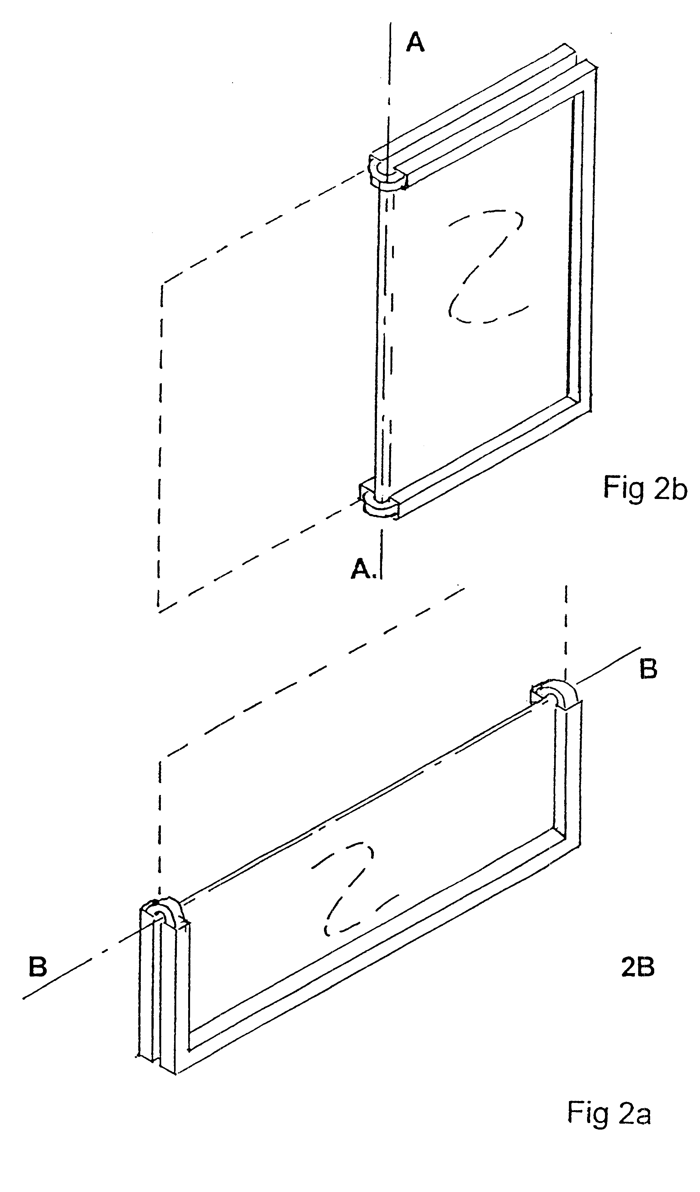
  • Portable visual display device with a collapsible presentation screen
  • Portable visual display device with a collapsible presentation screen
  • Portable visual display device with a collapsible presentation screen

Examples


Embodiment Construction

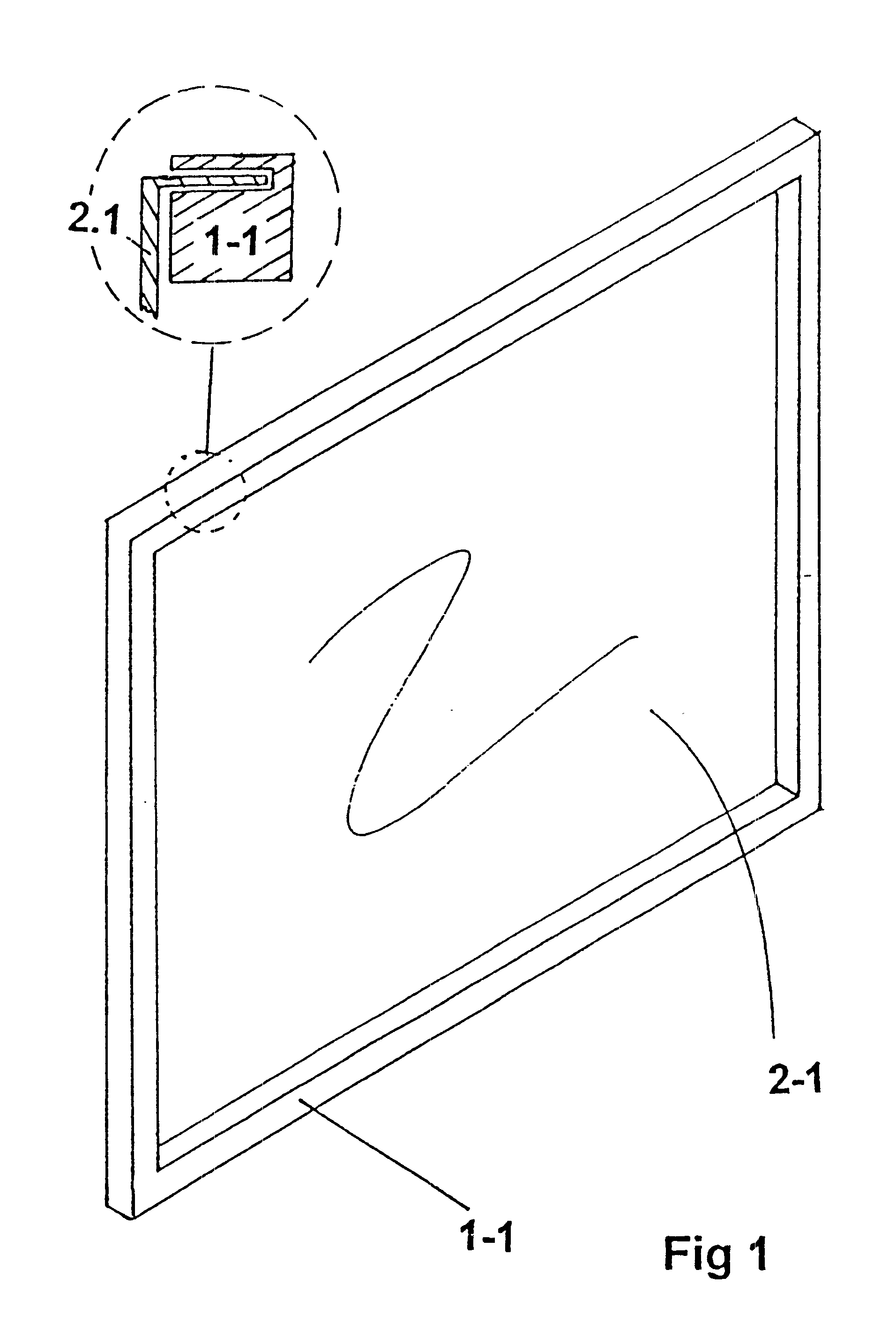
FIG. 1 is a perspective drawing that shows an example of a general visual display screen assembly wherein a rectangular supporting frame member (1-1) supports the screen member (1-2) that is permanently attached (except for replacement purposes) to the surrounding frame member. The screen member is held to be flat within the frame member (1-1) by its being attached to the four sides of the frame member. The frame member can be considered to comprise the two upstanding side elements and the upper and lower horizontal elements. A magnified cross-section of the frame and screen members is shown for clarity and illustrates a simple example attachment method using a push-in mounting of the screen member into a slot in the frame member.

The material of the screen member may be of a passive translucent nature suitable for the diffusion of optical images projected through the screen member from a projection device located to the rear of the screen member.

Embodiments of a collapsing screen as...


PUM


Abstract

A colapsible rear projectrion screen assembly for a portable visual display device. Embodiments are presented that include a flexible screen supported by a surrounding rigid screen that collapses by a ssimple folding movement for easy transport while also removing any risk of opticql or physical damage to the screen member material in the collapsing process.

Description

1. Field of the InventionThe invention relates to a presentation screen for the presentation of still or moving visual images such as pictures, text or data to a group or a number of people in typical and everyday business, training, education, promotion or exhibition environments. The screen is of the diffusion type, using diffusion means for displaying the images on the front viewing surface. The screen may collapse into a smaller configuration such as to significantly increase its portability as required for being readily moved from room to room or travelling from place to place. The field of the invention also relates to the various forms of art that may be employed in its various embodiments as, or as part of, a visual display device.The field of this invention is that of flexible, rear projection screens and is not intended to include front (i.e. reflective) display screen applications, active display screens or rigid screens.2. Description of Prior ArtVisual Display by means ...

Claims


Application Information

Patent Timeline
IPC IPC(8): G03B21/30H04N5/74G03B21/58
CPCG03B21/30H04N9/3141
Inventor MADDOCK, ALAN
Owner DISPLAYKINETICS
Learn More