
Dot dropout inspection method and printer, and recording medium storing program therefore

a technology of inspection method and printer, which is applied in the direction of digital output to print units, printing, other printing apparatuses, etc., can solve the problems of affecting image quality, nozzle clogging, and inability to jetting ink droplets,

Inactive Publication Date: 2002-09-24
SEIKO EPSON CORP
View PDF12 Cites 13 Cited by
  • Summary
  • Abstract
  • Description
  • Claims
  • Application Information

AI Technical Summary

Benefits of technology

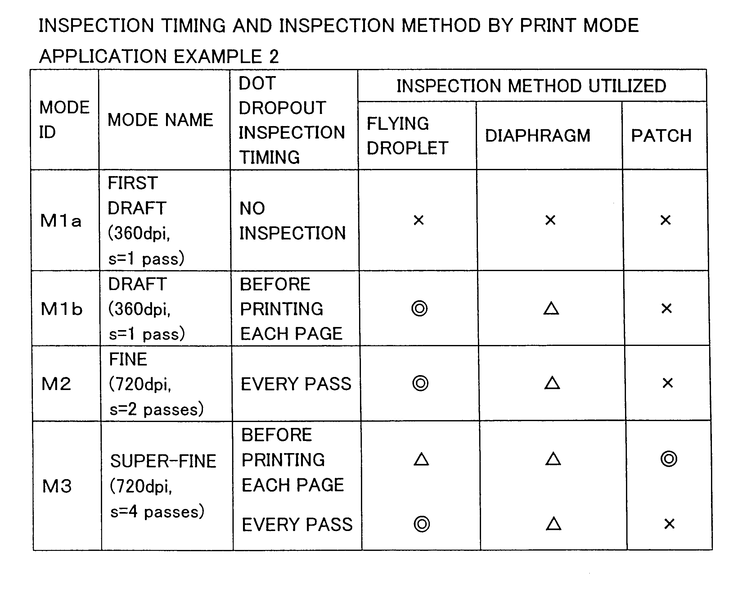
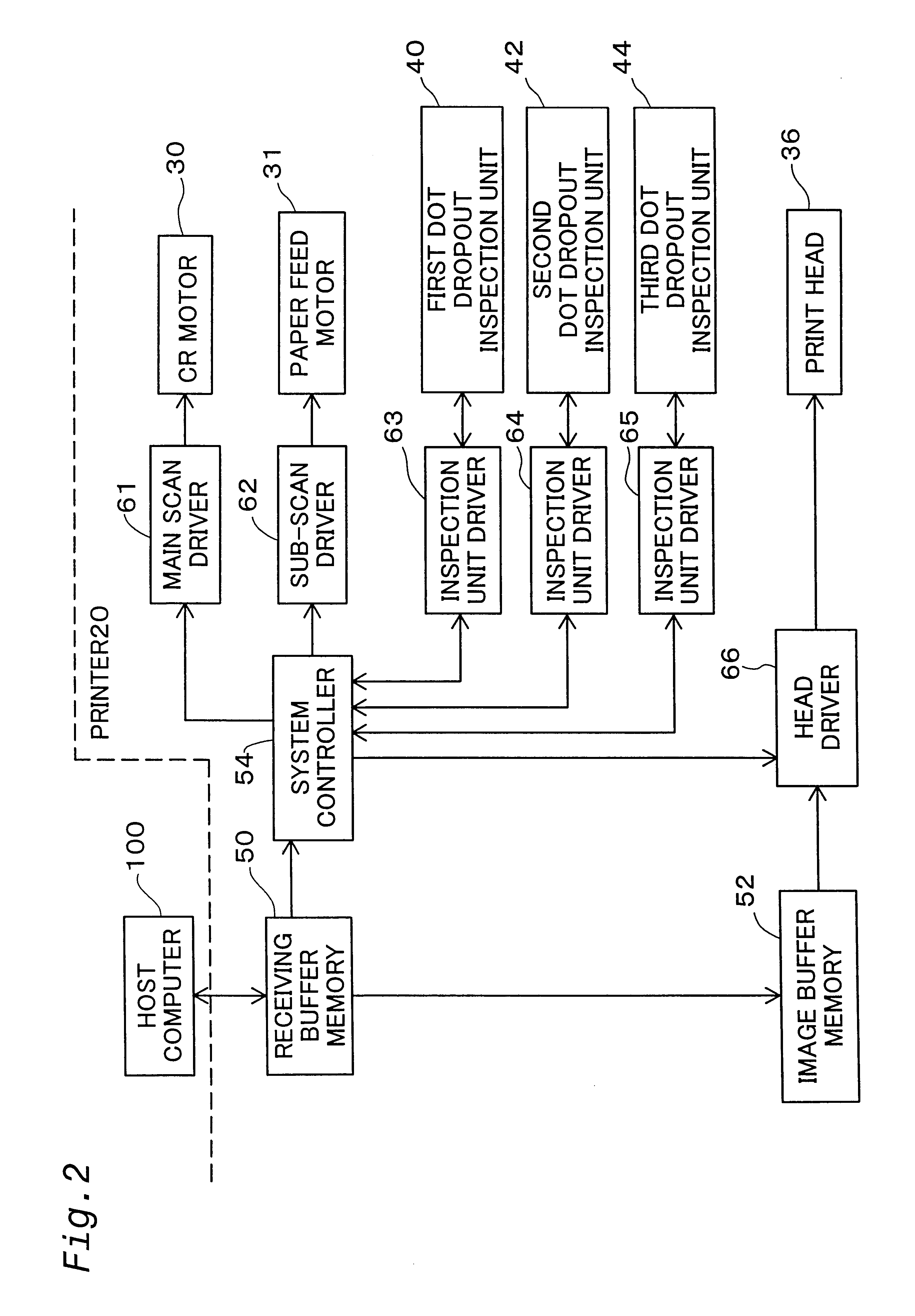
Such an operation makes it possible to set a preferable combination of dot dropout inspection timing and inspection principle matched to the print mode, and thereby reliable dot dropout inspection can be conducted as necessary.
Further, only nozzles actually used in the printing operation may be selected for targets of the inspection. This enables the inspection time to be shortened.

Problems solved by technology

Due to an increase in ink viscosity and / or bubble entrainment and the like, some of the nozzles may clog and become incapable of jetting ink droplets.
Nozzle clogging degrades image quality by causing dot dropout within the image.
Therefore, when nozzles have clogged and no dot dropout inspection is carried out before printing in the high-image-quality print mode, dot dropout may occur and make it impossible to obtain the desired image quality.
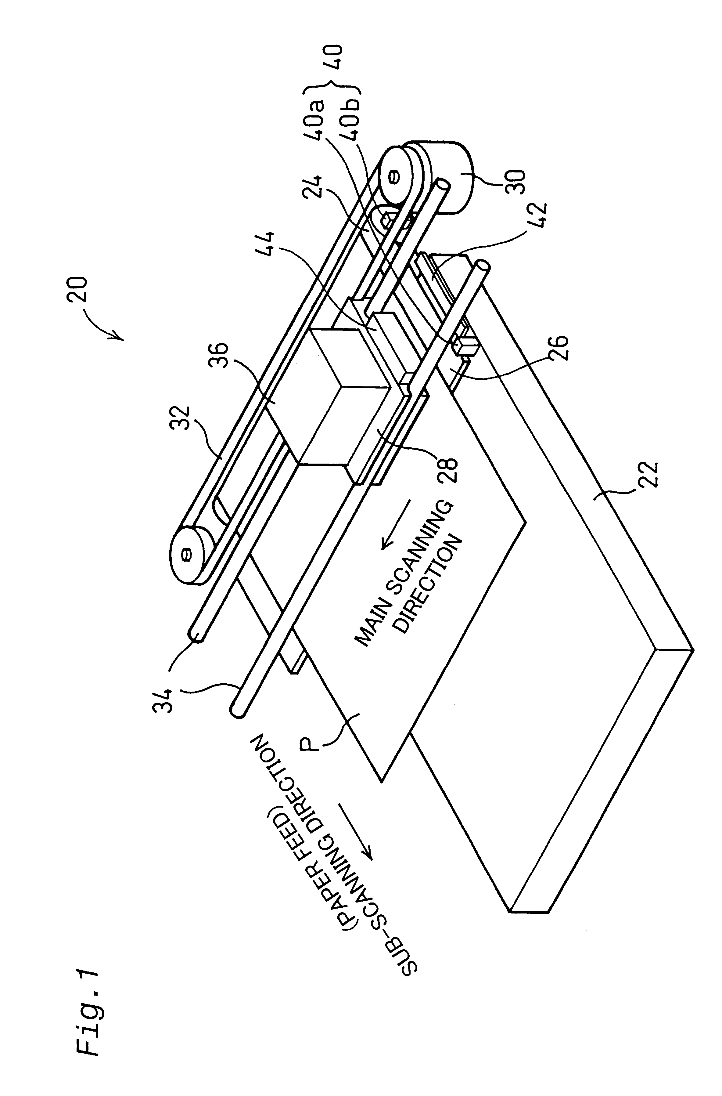
When the light beam L is not blocked whatsoever during the nozzle drive period, it can be judged that the nozzle is clogged.
If ink droplets Ip are simultaneously jetted from adjacent nozzles, however, erroneous detection may occur due to interference between adjacent diaphragms 42a.
If the color of the illumination light beam L is red, good detection of inks with colors near red (dark magenta M.sub.D, light magenta ink M.sub.L, yellow ink Y.sub.D) may be impossible.

Method used


Image

  • Dot dropout inspection method and printer, and recording medium storing program therefore
  • Dot dropout inspection method and printer, and recording medium storing program therefore
  • Dot dropout inspection method and printer, and recording medium storing program therefore

Examples


Embodiment Construction

shown in FIG. 7(A), the printer 20 is assumed to be capable of using three print modes: draft (high speed, low image quality) mode M1, fine (medium speed, high image quality) mode M2, and super-fine (low speed, very high image quality) mode M2. Draft mode M1 has a print resolution of 360 dpi and a scan repetition number s (explained below) of 1. The fine mode M2 has a print resolution of 720 dpi and a scan repetition number s of 2. The super-fine mode M3 has a print resolution of 720 dpi and a scan repetition number s of 4.

FIGS. 8(A)-8(C) illustrate how individual pixels are recorded on a single raster line (main scanning line) in the three print modes M1-M3. The "scan repetition number s" means the number of main scans executed to record all pixels on a single raster line. Thus, as shown in FIG. 8(A), in draft mode M1, which has a scan repetition number s of 1, all pixels on a single raster line are recorded in a single main scan. As shown in FIG. 8(B), in fine mode M2, which has a...


PUM


Abstract

A system for inspecting nozzles jetting ink droplets for detecting clogging of nozzles in a printer. Different timings during different printing operations for conducting the inspection are preset with respect to at least two print modes among a plurality of print modes usable in the printer. Alternatively, different combinations of timings for conducting the inspection and inspection principles are preset with respect to at least two print modes among the plurality of print modes. When printing is performed according to a print mode selected from among the at least two print modes, the printer conducts the inspection at the timing and / or the inspection principle preset with respect to the selected print mode.

Description

1. Field of the InventionThe present invention relates to a technology for printing images by jetting ink droplets from each of a plurality of nozzles to record dots on the surface of a printing medium, and particularly to a technology for inspecting whether or not ink droplets are jetted from the individual nozzles.2. Discussion of the BackgroundAn inkjet printer prints images by jetting ink droplets from a plurality of nozzles. The print head of an ink jet printer is equipped with a large number of nozzles. Due to an increase in ink viscosity and / or bubble entrainment and the like, some of the nozzles may clog and become incapable of jetting ink droplets. Nozzle clogging degrades image quality by causing dot dropout within the image.The background way of inspecting for nozzle clogging is for the user to print a special test pattern on printing paper before starting the printing operation and to then examine the printed test pattern visually.Most printers have a plurality of printi...

Claims


Application Information

Patent Timeline
IPC IPC(8): B41J2/045B41J2/505B41J2/165G06F3/12B41J2/01B41J2/21
CPCB41J2/0451B41J2/04551B41J2/04561B41J2/04573B41J2/04581B41J2/2139B41J2/5056
Inventor ENDO, HIRONORI
Owner SEIKO EPSON CORP
Learn More