Heat recovery procedure

a heat recovery and heat recovery technology, applied in the field of improved heat recovery procedures, can solve the problems of glycol becoming a pollution problem, heat loss of cooling water,

Inactive Publication Date: 2002-09-17
SD LIZENZVERWGMBH
View PDF3 Cites 29 Cited by
  • Summary
  • Abstract
  • Description
  • Claims
  • Application Information

AI Technical Summary

Problems solved by technology

In addition to heating the Absorber feed gas, it is also necessary to cool the gas from the Absorber to remove water before the gas can be returned to the ethylene oxide reaction system since water is detrimental to the catalyst in the reaction system.
The heat from cooling the gas is lost to cooling water.
The glycol becomes a pollution problem and provisions often are required to remove it.

Method used


Image

  • Heat recovery procedure

Examples


Embodiment Construction

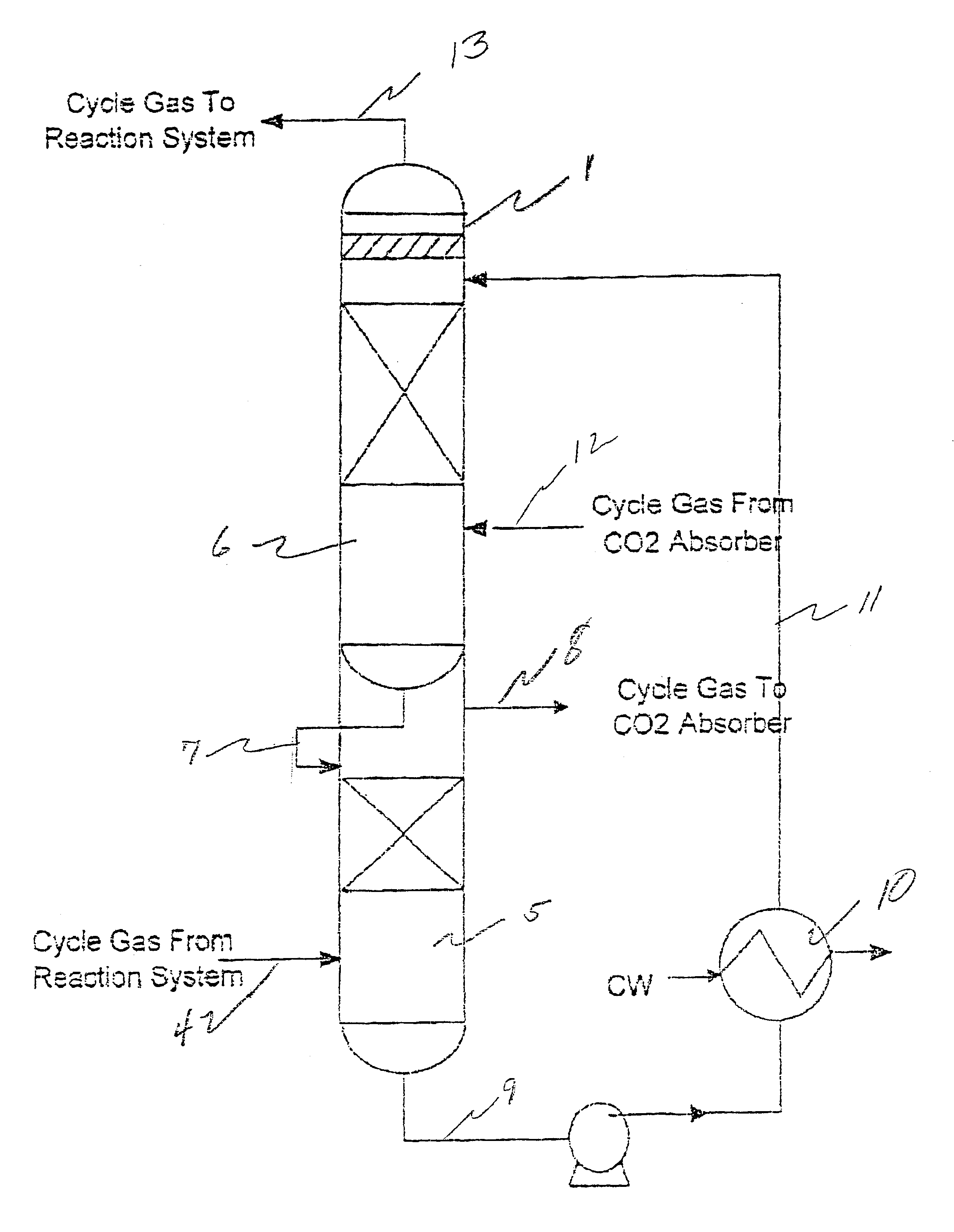
In a 600,000 MT / YR ethylene oxide plant the stream 4 cycle gas from the reaction system after ethylene oxide scrubbing is 13,300 kg-moles / hr for a low CO.sub.2 design with a typical composition of 2.2 vol % CO.sub.2 and a water content of 0.39 vol %. The residual ethylene oxide content is 30 vol ppm. The temperature is 41.degree. C. and the pressure is 20.0 bars. The water circulation stream 7 would be approximately 70,400 kg-moles / hr at a temperature of 43.degree. C. The circulation water stream after it leaves the gas cooling section 6 has been heated to 79.3.degree. C. This water is contacted with the cycle gas ie. packed section 5 of presaturator 1. The gas is heated to 77.degree. C. and the liquid is cooled to 57.degree. C. Approximately 28.2 million kcals are transferred from the liquid to the gas. The gas temperature is raised to 77.degree. C. and the water content is raised to 2.12 vol. %. The ethylene oxide content of the gas feed to the CO.sub.2 absorber is reduced by 60%....


PUM

PropertyMeasurementUnit
temperatureaaaaaaaaaa
pressureaaaaaaaaaa

Abstract

The present invention provides a process treating the cycle gas from an ethylene oxide reactor to avoid heat losses in a carbonate scrubbing system as well as glycol formation in the carbonate scrubbing and catalyst contamination upon cycle gas recycle.

Description

1. Field of the InventionThe present invention relates to an improved heat recovery procedure in an ethylene oxide process carbon dioxide removal system.2. Description of the Prior ArtIn processes such as those where ethylene oxide is formed by the oxidation of ethylene with molecular oxygen, carbon dioxide is also produced during the oxidation. It is necessary that the carbon dioxide so produced be separated in order to prevent a build up of this product. See U.S. Pat. No. 3,523,957.The removal of carbon dioxide from an ethylene oxide reaction system is generally done in a Hot Carbonate System (Potassium Carbonate Scrubbing System) where all or a portion of the reaction gas is sent to a CO.sub.2 Absorber after the product ethylene oxide has been removed from the gas by water scrubbing in a Scrubber. The scrubbed cycle gas from the reaction system after ethylene oxide removal is normally cold as it is at Scrubber temperatures or slightly higher if it has been recompressed after scru...

Claims


Application Information

Patent Timeline
Patent Type & Authority Patents(United States)
IPC IPC(8): C07D303/04C07D301/00C07D301/32C07D303/00C07D301/08C07D301/04
CPCC07D301/08C07D301/32C07D303/04Y02P20/50C07D301/04
Inventor BILLIG, BARRYMANN, JAMES
Owner SD LIZENZVERWGMBH
Why Eureka
Try Eureka