
Linear illumination unit having plurality of LEDs

a technology of leds and linear illumination, applied in the field of machine vision system, can solve the problems of large space occupation, large space occupation, and large volume of light sources

Inactive Publication Date: 2002-09-17
STOCKERYALE IRL
View PDF10 Cites 103 Cited by
  • Summary
  • Abstract
  • Description
  • Claims
  • Application Information

AI Technical Summary

Benefits of technology

to provide a line illuminator which has some or all of the following advantages:
allows configuration for a required application at the design and / or installation stages in a versatile manner.
In one embodiment, the housing allows spread of light in the linear direction beyond the ends of the housing.

Problems solved by technology

Additionally, the physical size of the illuminator is very important, as for some vision systems there is very little physical space available.
Such light sources are generally expensive to install and to maintain and a further problem is that they are quite bulky.
Such light sources are also quite bulky and expensive, and suffer from limited source lifetime and other problems.
In general, the light from these packages has a cross-sectional profile which is such that it can not be described by a smooth mathematical function such as a Gaussian function, but has undesirable intensity variations caused by the structure of the LIED chip and / or by the arrangement of the LED within the optical elements of the package.
There is the potential for a lot of structure (non-uniformity) in the illumination pattern which is produced when these packaged LEDs are used to make an illuminator depending upon how well the beams from the individual LEDs mix.
This can be improved by adding diffuser material either within the individual LED packages or on the exterior of the housing of the illuminator, but the effect in both circumstances is to reduce the efficiency of the system.
A problem with such illuminators is that the pointing accuracy of individual LEDs is poor, leading to lack of uniformity of the illuminated area.
Also, the uniformity of the light produced by the individual LEDs is poor, and even after they mix on the target, the resulting uniformity is poor, perhaps + / -25%.
Another disadvantage is that the overall brightness of the illumination is limited by the packing density of the individual packaged LEDs, which are typically housed in 5 mm or 3 mm diameter acrylic packages.
incorporates redundancy so that failure of some source!

Method used


Image

  • Linear illumination unit having plurality of LEDs
  • Linear illumination unit having plurality of LEDs
  • Linear illumination unit having plurality of LEDs

Examples


Embodiment Construction

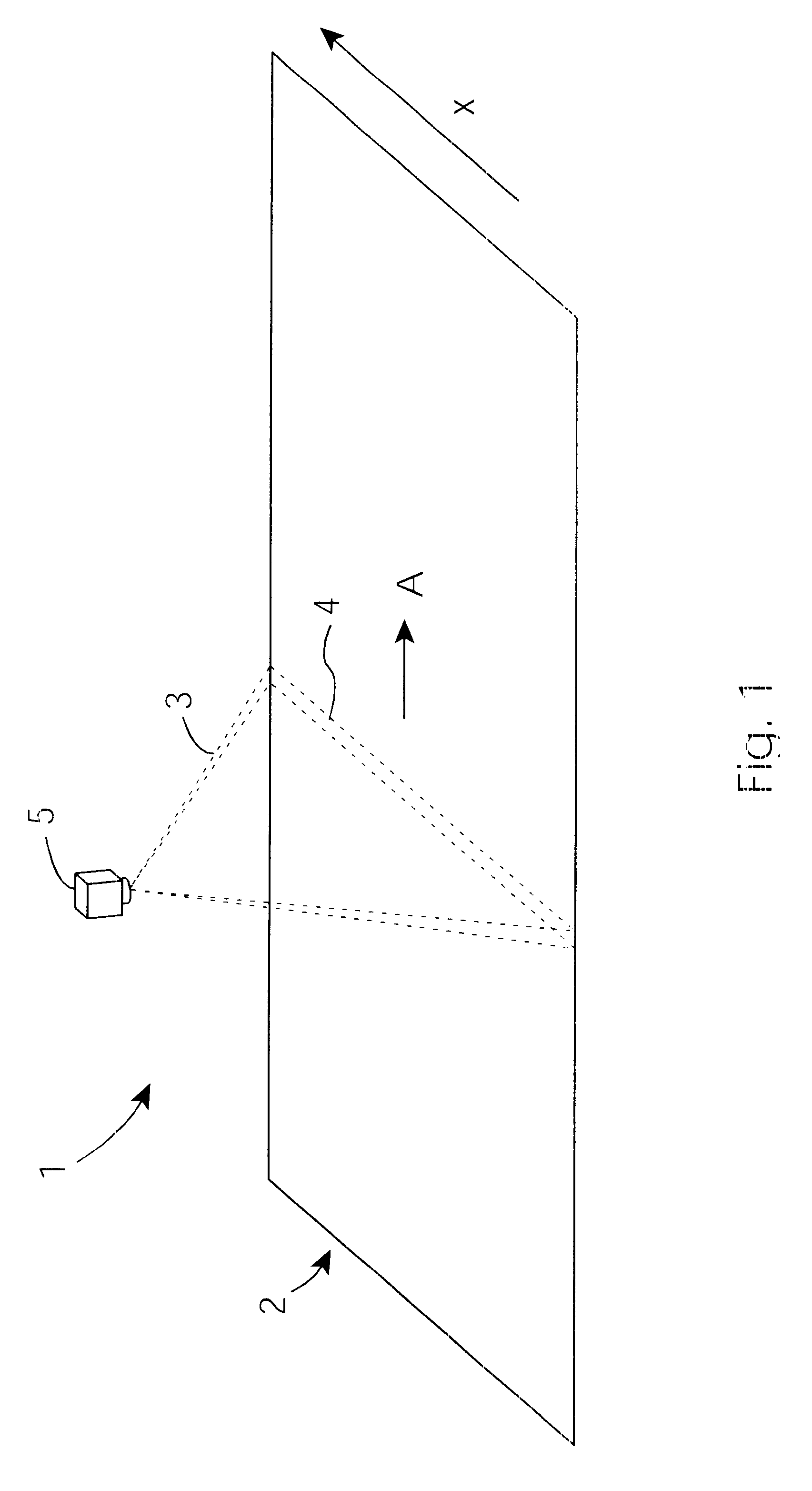
Referring to the drawings, and initially to FIG. 1 there is shown a diagrammatic perspective view of a web application showing the typical field of view of a linescan camera in relation to the web. A web 2 moves in the direction of the arrow A and conveys items which are being inspected. The web is inspected by a camera, typically a linescan camera 5, or an array of linescan or other cameras. The field of view of the camera or cameras is typically a long (several hundred millimetres up to tens of metres) narrow ( several millimetres or less) strip or line 4. The direction along the line, the linear direction, is shown as the x axis on FIG. 1.

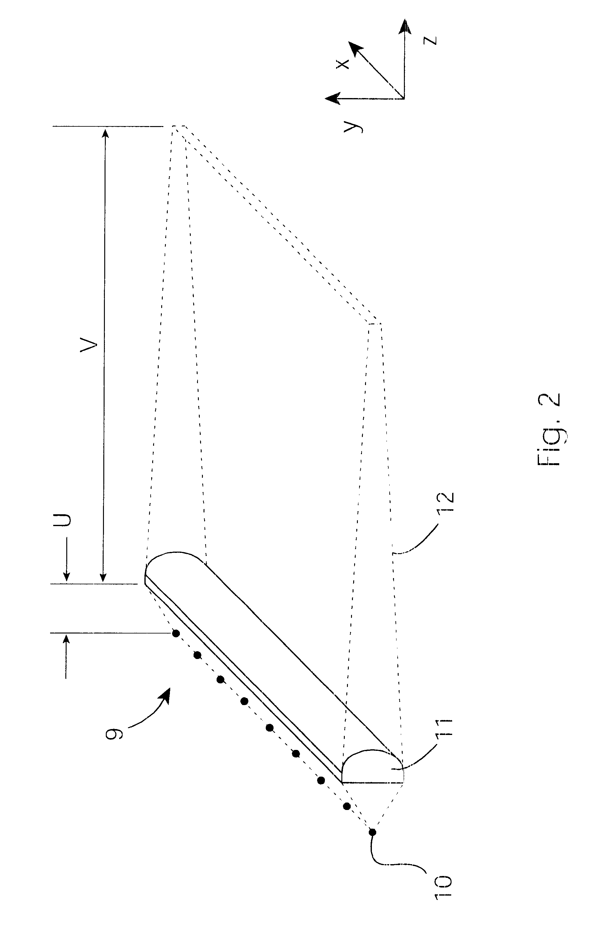
Referring now to FIG. 2 a lighting unit 9 of the invention is illustrated in diagrammatic form. A source of light 10 emits light which is focused by a cylindrical lens 11 to provide a projected line of light 12. The key spacing parameters are "u" which is the separation between the source 10 and the lens 11 and "v" which is. the distance between...


PUM


Abstract

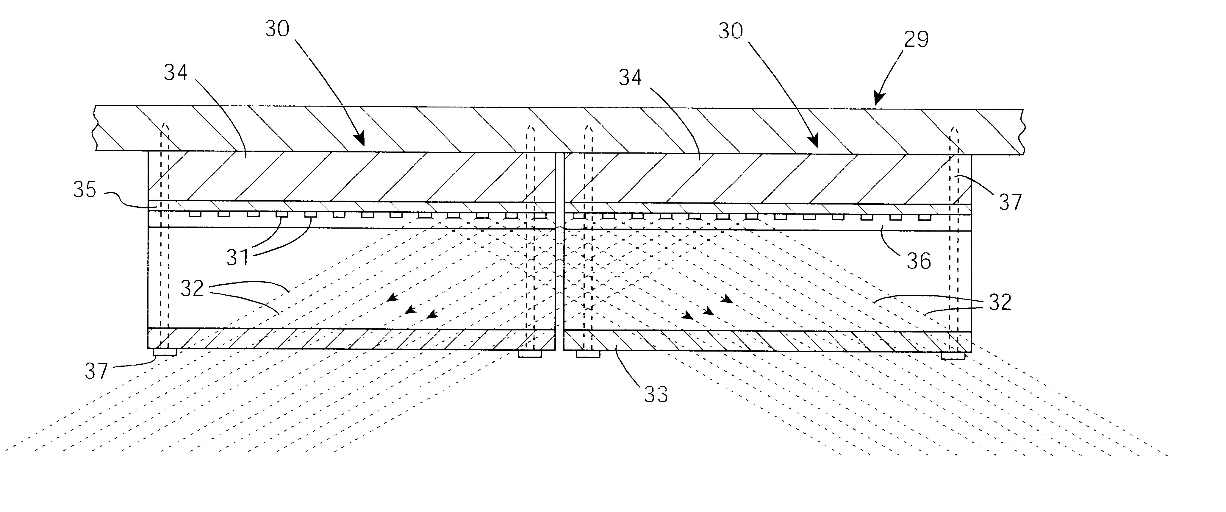
A linear illumination unit (30) has a line of unlensed LEDs (31) which emit light spreading out. The light is focused into a line by a Fresnel lens (33) which allows spread and mixing of light in the linear direction and limits spread in the ortliogonal direction. A Fresnel lens is particularly effective for this purpose. The housings 34 have slots 36 to help control light spread, and the housings are open-ended to allow spread of light in the linear direction beyond the confines of the, geometry of the units. Thus, units (30) may be interconnected to provide seamless linear light in a modular manner.

Description

The invention relates to linear illumination. Such illumination is required, for example, for "web" applications in which items are conveyed on a web and are inspected by a camera. Typically, a linescan camera is used in this application. Since the linescan camera is inspecting a narrow strip of the web, transverse to its direction of motion, the requirement for the illumination source is that it illuminate the appropriate strip of material to the brightness level which is required. Exaiyiplics of web inspection are inspection of surfaces of ceramic tiles, print media, electronic components on printed circuit boards (PCBs), paper, and pharmaceutical packaging. It may also be used for sorting or grading of fruit and vegetables. Another application is scanners, in which the light source moves rather than the target.PRIOR ART DISCUSSIONA typical machine vision system consists of an illuminator, a camera, and a control system for enabling the illuminator and camera in combination to cap...

Claims


Application Information

Patent Timeline
IPC IPC(8): F21V5/04F21V5/00G01N21/88G01N21/89F21V8/00H04N1/04
CPCF21V5/045G01N21/8806G01N21/8901F21Y2101/02Y10S362/80F21Y2115/10F21V5/10
Inventor KELLY, WILLIAM
Owner STOCKERYALE IRL
Learn More