
Blood pressure monitor and pulse wave detection apparatus

a technology of blood pressure monitor and detection apparatus, which is applied in the field of blood pressure monitor and pulse wave detection apparatus, can solve the problems of not applying pressure sufficient to impart unpleasant or disagreeable feelings to subjects

Inactive Publication Date: 2002-08-13
SEIKO EPSON CORP
View PDF11 Cites 31 Cited by
  • Summary
  • Abstract
  • Description
  • Claims
  • Application Information

AI Technical Summary

Benefits of technology

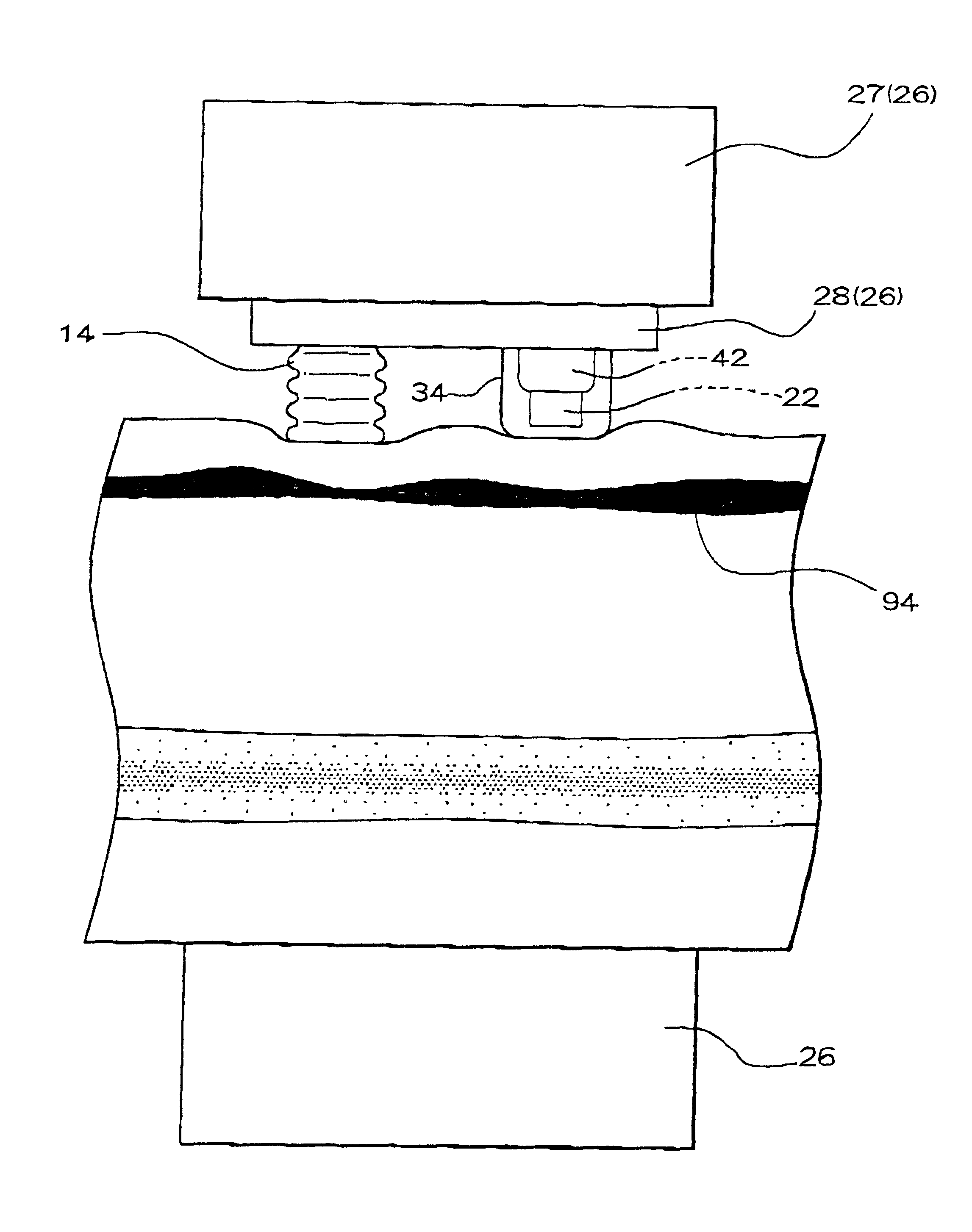
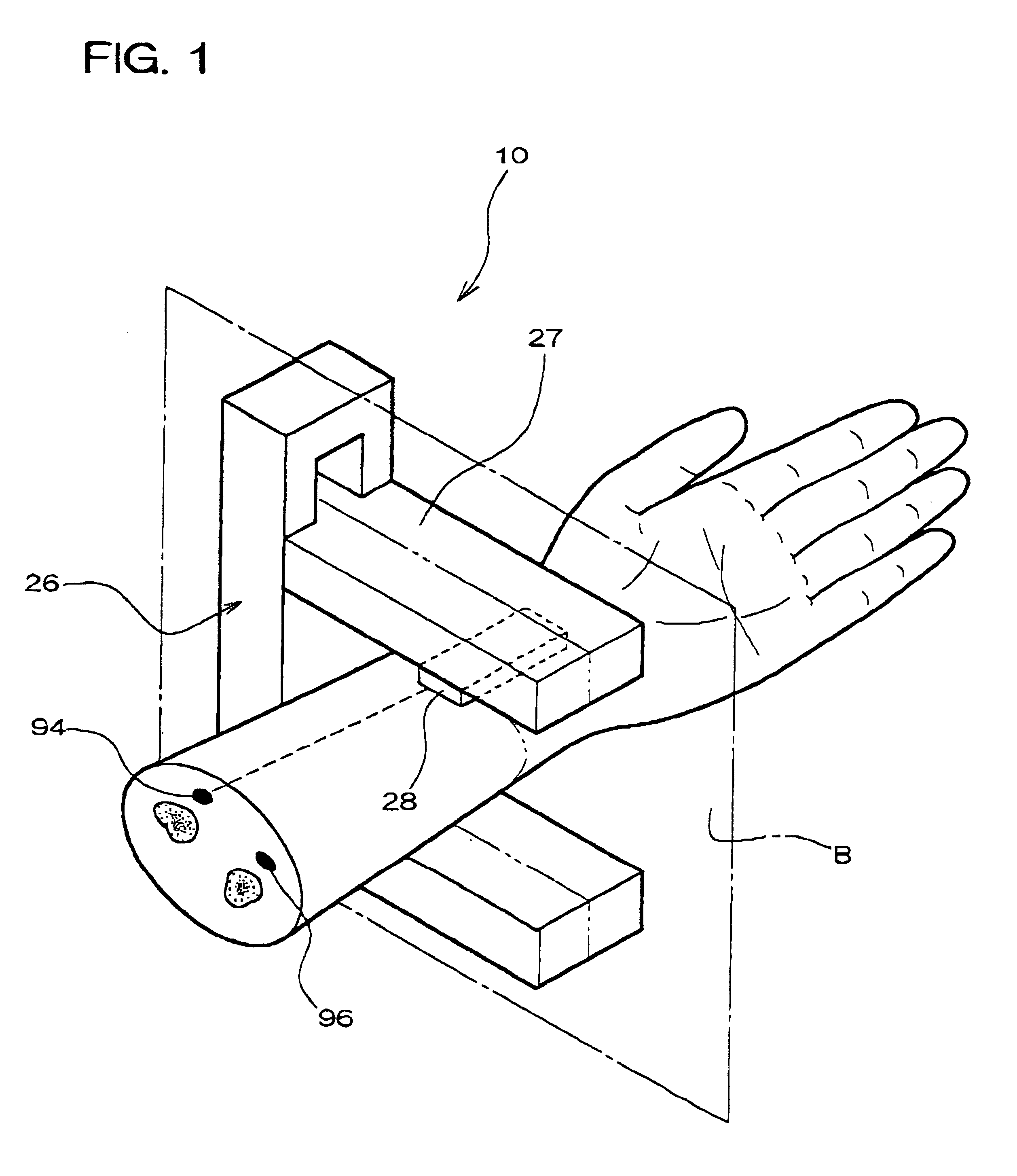
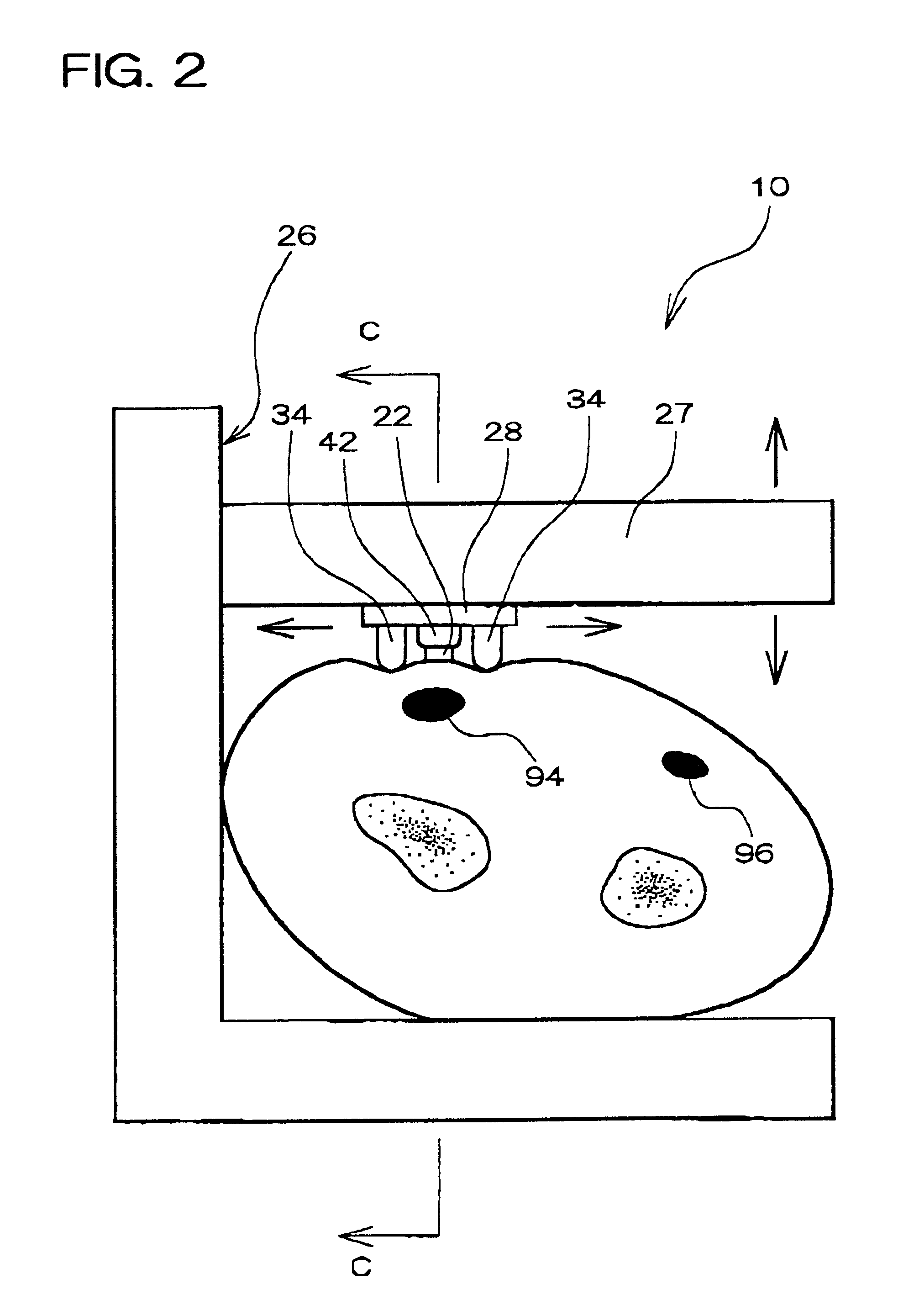
In addition, because the artery pressing section presses the artery only locally, the pressing operation will not be interfered with by the sinews or bones which may be present close to the artery. Therefore, the pressing operation can press the artery with certainty, ensuring measurement of the blood pressure more accurately than in the conventional method in which the entire circumference of the extremities or fingers is pressed by a cuff or the like.
a control section which controls the pressing force applied to the artery by the artery pressing section so as to gradually increase the pressing force from a predetermined minimum pressing force;

Problems solved by technology

In these blood pressure measuring methods, however, almost the entire circumference of the brachium or wrist is pressed so that the nervous tissues which are distributed densely close to funny bones in the case of the wrist, for instance, are pressed, imparting an unpleasant and disagreeable feeling.
Such an unpleasant and disagreeable feeling caused by pressing the entire circumference of the measuring section such as the extremities and fingers has been experienced when the blood pressure is measured by pressing the entire circumference of other parts such as brachium and fingers.
As a result, a pressure sufficiently great as to impart an unpleasant or disagreeable feeling to the subject will not be applied.

Method used


Image

  • Blood pressure monitor and pulse wave detection apparatus
  • Blood pressure monitor and pulse wave detection apparatus
  • Blood pressure monitor and pulse wave detection apparatus

Examples


second embodiment

2. Second Embodiment

The second embodiment differs from the first embodiment in that this embodiment uses a pulse wave sensor instead of the vibration sensor, is provided with a conversion section for converting a pulse wave into a blood pressure waveform, and a blood-pressure-waveform processing section for introducing various indicators based on the blood pressure waveform, and has a notification section which can provide not only information on the maximum and minimum blood pressures, but also information on the blood pressure waveform converted by the conversion section and various indicators introduced by the blood-pressure-waveform processing section. Other features are the same as in the first embodiment, so description thereof is omitted corresponding sections in each figure are indicated by the same symbols as in the first embodiment.

2.1 Configuration of Blood Pressure Monitor

In the same manner as in the first embodiment, the blood pressure monitor of this embodiment is prov...

third embodiment

3. Third Embodiment

The third embodiment differs from the first embodiment in that the former blood pressure monitor is provided with a second artery pressing section. Other features are the same as in the first embodiment, so description thereof is omitted. Corresponding sections in each figure are indicated by the same symbols as in the first embodiment.

3.1 Configuration of Blood Pressure Monitor

In the same manner as in the blood pressure monitor 10 of the first embodiment, the blood pressure monitor 76 of this embodiment is provided with a mounting mechanisms 26 as a positioning mechanism, guides 34, an artery pressing section 14 as a first artery pressing section, a sensor pressing section 42, a control section 18, a blood pressure determination section 30, and a notification section 62.

FIG. 14, which corresponds to FIG. 2 for the first embodiment, is a cross section view showing blood pressure measurement using the blood pressure monitor 76 of this embodiment. FIG. 15 is a block...

fourth embodiment

4. Fourth Embodiment

The pulse wave detection apparatus of the fourth embodiment differs from the first embodiment in that the former is equipped with a pulse wave sensor in place of a vibration sensor, has no blood pressure determination section, and has a waveform processor. Other features are the same as in the first embodiment, so description thereof is omitted. Corresponding sections in each figure are indicated by the same symbols as in the first embodiment.

4.1 Configuration of Pulse Wave Detection Apparatus

In the same manner as in the first embodiment, the pulse wave detection apparatus 84 of this embodiment is provided with a mounting mechanism 26 as a positioning mechanism, guides 34, an artery pressing section 14, a sensor pressing section 42, a control section 18, and a notification section 62. The external appearance may be the same as the first embodiment.

FIG. 17 is a block diagram showing the electric configuration of the pulse wave detection apparatus 84 of this embodi...


PUM


Abstract

The blood pressure monitor (10) comprises an artery pressing section which locally presses an artery of the extremities or fingers at an arbitrarily variable pressing force, a vibration sensor (22) detecting a vibration of the artery at the pressed point or points on a peripheral side thereof, a mounting mechanism (26) which positions the artery pressing section and the vibration sensor (22) on the artery, a blood pressure determination section which determines the maximum and minimum pressures based on various pressing force values applied by the above-mentioned artery pressing section and signals detected by the vibration sensor (22) at these various pressing force values, guides (34) which are provided on each side of the vibration sensor (22) and guide the vibration sensor (22) to the artery by being located on the both sides of the artery, and a peripheral side pressing section which presses the artery on the peripheral side from the vibration sensor (22).The blood pressure monitor (10) does not impart an unpleasant or disagreeable feeling to the subject.

Description

The present invention relates to a blood pressure monitor and pulse wave detection apparatus.BACKGROUND OF THE ARTBlood pressure is commonly measured by auscultation which consists of applying a pressing force greater than the maximum blood pressure to the artery by pressing the brachium or wrist around the circumference and detecting a vibration of the pressed artery on the peripheral side, while gradually decreasing the pressing force.A blood pressure monitor disclosed in Japanese Patent No. 2804484, for example, has a means of detecting displacement of the cuff for applying pressure around the wrist.Japanese Patent Application Laid-open No. 5-300885 discloses a blood pressure monitor designed as shown in FIG. 2 of the published document, wherein the arterial blood flow is controlled by the pressing force applied to the arm by altering the degree of expansion of an air bag 7 which consists of section of a cuff wound around the arm. This pressing force is monitored by a third press...

Claims


Application Information

Patent Timeline
IPC IPC(8): A61B5/021A61B5/0225
CPCA61B5/021A61B5/02116A61B5/0225A61B5/6843A61B5/6824
Inventor AMANO, KAZUHIKO
Owner SEIKO EPSON CORP
Learn More