
Capotasto

a technology of capotasto and capotasto, which is applied in the field of capotasto, can solve the problems of impaired tuning of instruments, unsatisfactory capos with respect to one or more of the above requirements,

Inactive Publication Date: 2002-06-25
STERNER ANDERS
View PDF6 Cites 13 Cited by
  • Summary
  • Abstract
  • Description
  • Claims
  • Application Information

AI Technical Summary

Benefits of technology

Further embodiments of the inventive capotasto are that the other end of the tensioning strap is designed to generate an initial displacement effect that causes a neck corner to be driven into a corner angle as parts of the fastening means are brought into fastening engagement.
The other end-part of the tensioned strap is configured and directed so that when in contact with the adjacent peripheral part of the neck of the instrument it generates a wedging effect which causes the capo to be displaced so that said corner receives the adjacent corner of the neck as the parts of the fastening means are fastened together.
Because the capotasto strap has a memory form and a degree of springiness such that the capotasto will lie shape-bound around the neck of the instrument even though subjected to gravitational forces, the capo will not fall from the neck of the instrument even when the fastening device is open. When open, the capotasto will normally be free to move along the neck of the instrument while, as before mentioned, the components of the fastening means are constantly in the immediate vicinity of each other and therewith readily fastened by the user.
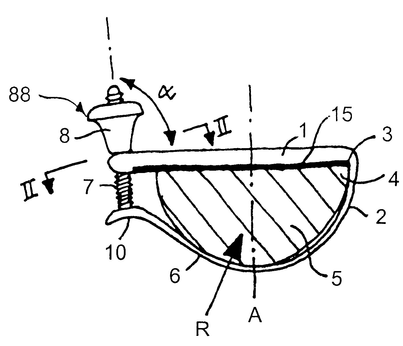
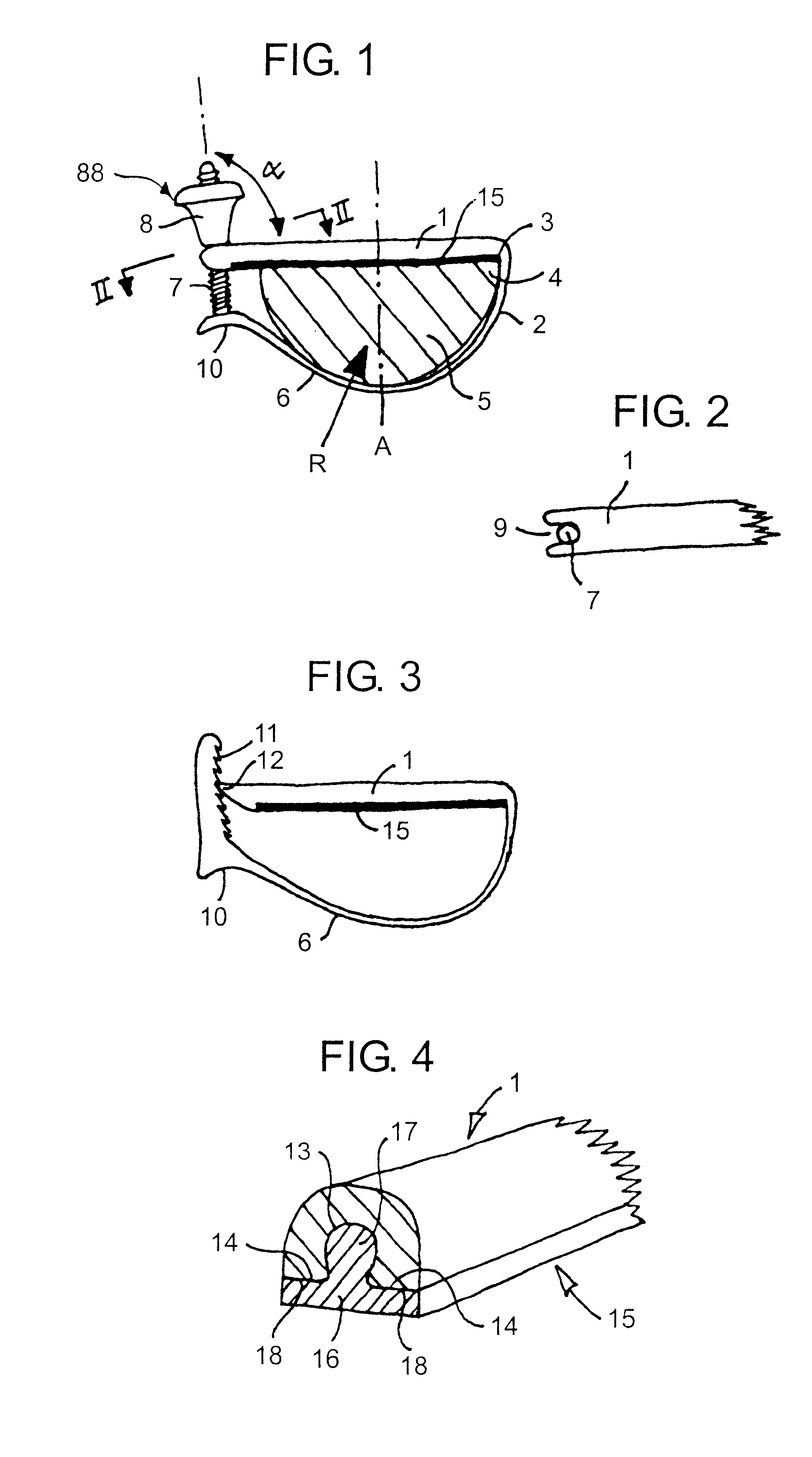
The tensioning strap is elastically flexible in at least that end-part which connects with the one end of the bar. The one end of the tensioning strap is connected to the bar so as to be flexurally rigid at the connection point and is directed so as to diverge from the undersurface of the neck when the strap is not under tension. As a result, the capotasto will project minimally beyond the cross-sectional profile of the neck of the instrument on the discant side, while the adjacent outer edge of the fingerboard is received stably in the corner defined by the bar and the tensioning strap. Furthermore, the force resultant of the contact forces of the tensioning strap against the underside of the neck will be directed generally towards the corner angle, therewith holding the capo stably in its set position on the neck of the instrument. The aforesaid corner also forms an anvil means against which the edge of the fingerboard is placed when fastening the capotasto. This eliminates the risk of the strings being pulled obliquely by the capo as it is being secured to the instrument (this being one cause of undesirable pitch changes).
Although the inventive concept can be applied with several earlier types of capo, it is preferred that the fastening means of the capo is located at that end of the bar which lies opposite to the end that carries the tensioning strap, so that the fastening means will be able to fit in the gap between the finger tips and thumb of one hand with said hand placed typically around the neck of the instrument and moved therealong. As a result of the position of the fastening means, the minimised projection of the bar on the discant side of the fingerboard, and because the capo as a whole can be given a very slender construction owing to the fact that the major part thereof is subjected to tension forces, a capo that is constructed in accordance with the inventive principle will encroach on the space of the user's hand only to a very small extent. This enables the capo bar to be placed close to the top of the gripping strap without impeding the hand to any appreciable extent. The gripping strap will then function as an anvil means and prevent the strings from being depressed more than is necessary. Another, and more common, reason why tuning of an instrument is impaired when using a capo (both in relation to accompanying instruments and to the individual strings of the instrument being accompanied) is precisely because the capo presses the strings down against the fingerboard to an unnecessary extent.
According to one particularly preferred embodiment of the invention, the essentially rigid capo bar is integral with the tensioning strap, wherein at least the end-part of the tensioning strap that adjoins the capo bar is semi-rigid (i.e. elastically flexible under the influence of the fastening means), wherein the end-part of the tensioning strap connecting with said fastener means is preferably given a slightly reduced flexural rigidity in the plane of the capo, wherein the end-part of the fastening strap carries an upwardly extending screw and is held in the immediate vicinity of or in engagement with a recess at the free-end of the capo bar, by virtue of the stiffness of the strap and its attachment to the capo bar, wherein a nut may be screwed onto the screw to enable the tensioning force generated by the capo to be adjusted. The nut may have a general conical shape, so as to enable it to be easily snapped into and out of engagement with the edge of the recess.

Problems solved by technology

The aforesaid known capos are unsatisfactory with respect to one or more of the above requirements.
This eliminates the risk of the strings being pulled obliquely by the capo as it is being secured to the instrument (this being one cause of undesirable pitch changes).
Another, and more common, reason why tuning of an instrument is impaired when using a capo (both in relation to accompanying instruments and to the individual strings of the instrument being accompanied) is precisely because the capo presses the strings down against the fingerboard to an unnecessary extent.

Method used


Image

  • Capotasto
  • Capotasto

Examples


Embodiment Construction

Further in scope of applicability of the present invention will become apparent from the detailed description given hereinafter. However, it should be understood that the detailed description and specific examples, while indicating preferred embodiments of the invention, are given by way of illustration only, since various changes and modifications within the spirit and scope of the invention will become apparent to those skilled in the art from this detailed description.

Shown in FIG. 1 is a rigid bar 1 which carries at one end a strap part 2 which extends generally at 90 degrees from said bar-end to form an inner corner 3 which receives a corresponding corner 4 on the neck 5 of the instrument, namely the side-edge corner of the fingerboard of said instrument (on the discant string side). It will be seen that the strap part 2 extends free from the undersurface of the neck, in the region that follows from the neck corner 4 down to the lower part of the neck 5.

The strap part 2 constit...


PUM


Abstract

A capo that includes a clamping bar (1) which is intended to extend transversely over the fingerboard on the neck of a stringed instrument, and a tensioning device which includes a resiliently bendable tensioning strap (6) whose one end-part (2) is essentially flexurally rigid and connects generally perpendicularly with one end of the bar (1). The other end can be detachably connected to the other end of the bar (1) with the aid of a fastening means (7, 8, 9; 11, 12), so as to clamp the bar (1) securely against the fingerboard with a desired clamping force. The tensioning strap (6) is free-standing from bar in its non-tensioned memory state, and the one end-part of the tensioning strap is directed at its connection with the bar in a manner such as to diverge from the undersurface of the neck when no tension is applied to the strap (6). The tensioning strap has in a non-tensioned state a memory form in which the strap holds the components of the fastening means (7, 8, 9; 11, 12) close to their mutual position of engagement. The tensioning strap (6) is pre-formed such that when initially tensioned, it will contact the neck in a peripheral region that lies beyond the symmetry plane of the neck (6) from a corner angle (3) between the one bar end and one end-part (2) of the strap, whereby a force resultant to the area of contact of the strap with the neck (6) strives to hold the neck corner (4) in engagement with the corner angle (3) and therewith tighten or tension the capo.

Description

1. Field of the InventionThe present invention relates to a capotasto of the kind with a clamping bar which is intended to extend transversely over the fingerboard on the neck of the stringed instrument.2. Prior ArtU.S. Pat. No. 5,016,514 teaches a capo which, according to one embodiment, includes a bar that has a recess at one end thereof. A straight highly elastic, plastic tubular member has an end part fitted on the bar and fixed thereto. The remainder of the tubular member extends around the neck of the instrument and has a screw at one end. The neck of the screw is received in a recess in the bar. The tensioned state of the capo can be adjusted, by screwing the screw deeper into the end of the tube. According to another embodiment of the capo taught by U.S. Pat. No. 5,016,514, the spring member includes a coiled tension spring and the bar includes a bore hole at each end. A screw extends through respective bore holes into the end of the coil spring. The coil spring is covered w...

Claims


Application Information

Patent Timeline
Patent Type & Authority Patents(United States)
IPC IPC(8): G10D3/00G10D3/04G10D3/053
CPCG10D3/043G10D3/053
Inventor STERNER, ANDERS
Owner STERNER ANDERS
Learn More