
Delivery assistance device

a technology of assistance device and fetus, which is applied in the field of obstetrical devices, can solve the problems of difficulty in properly placing the forceps, difficulty in locating the appropriate place on the fetus, and difficulty for the physician or other medical professional to properly place the forceps, etc., and achieves the effect of reducing or eliminating the inherent injuries, and quickly and easily removing

Inactive Publication Date: 2002-06-04
MEDISYS TECH
View PDF24 Cites 16 Cited by
  • Summary
  • Abstract
  • Description
  • Claims
  • Application Information

AI Technical Summary

Benefits of technology

It is another object of the invention to provide a device for assisting in the delivery of a fetus that will reduce or eliminate the injuries inherent in forceps or vacuum type assisted delivery systems.
It is still another object of the invention to provide a device for assisting in the delivery of a fetus that may be quickly and easily placed over the head of the fetus by the physician or other medical professional, and quickly and easily removed if necessary.
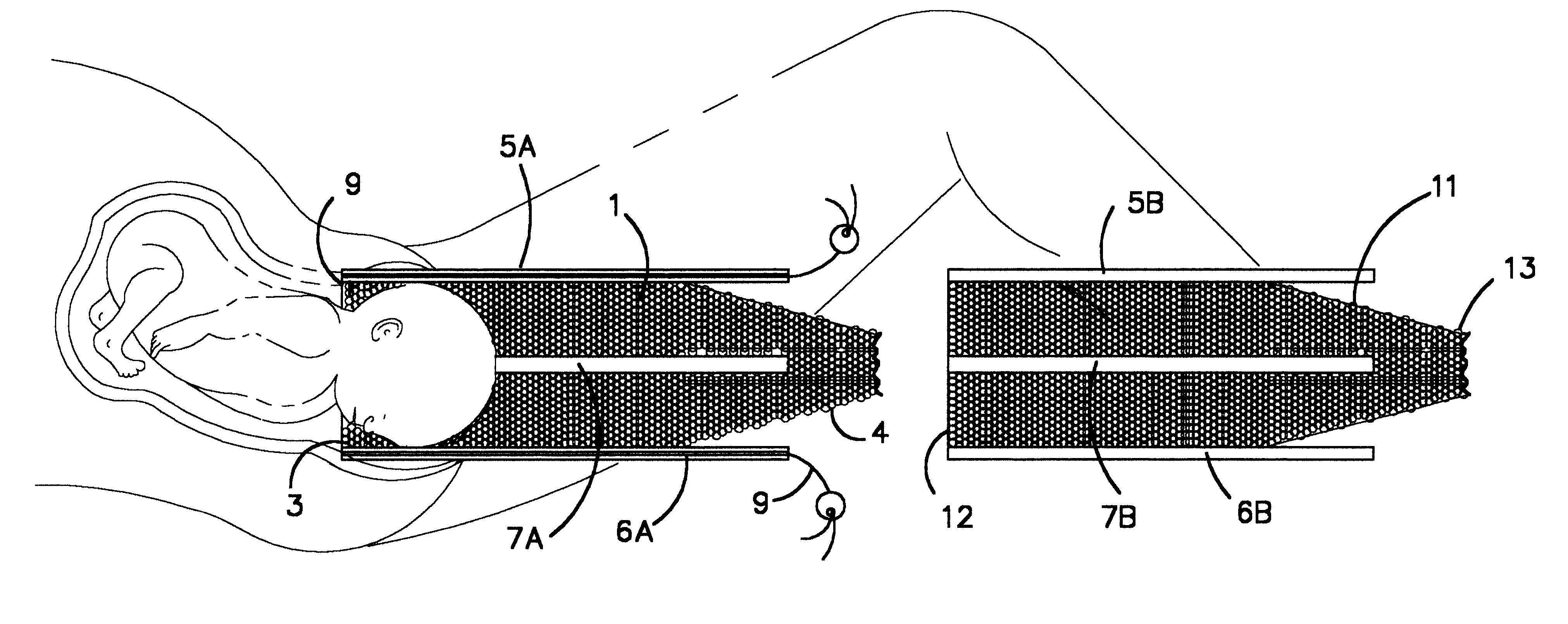
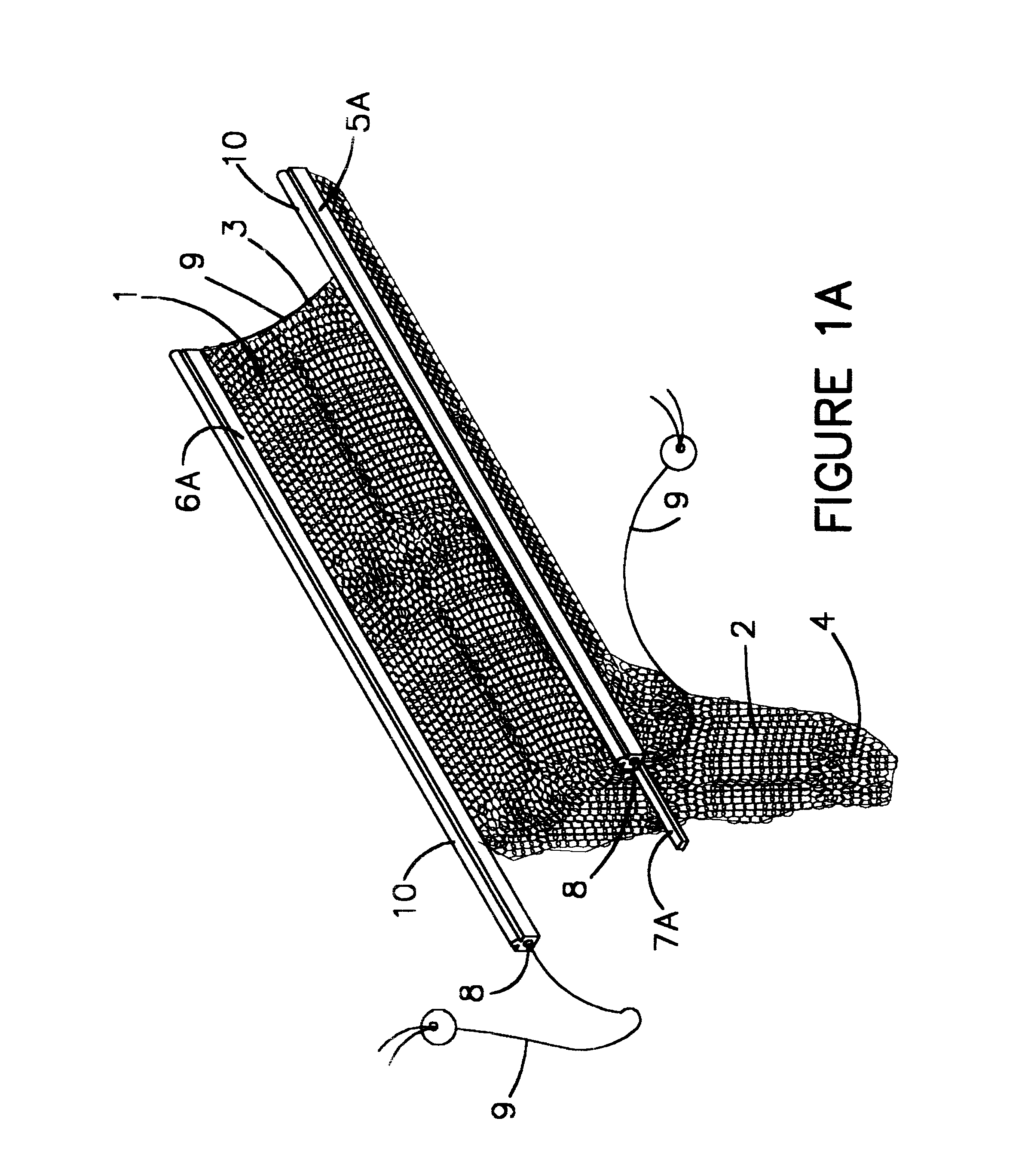
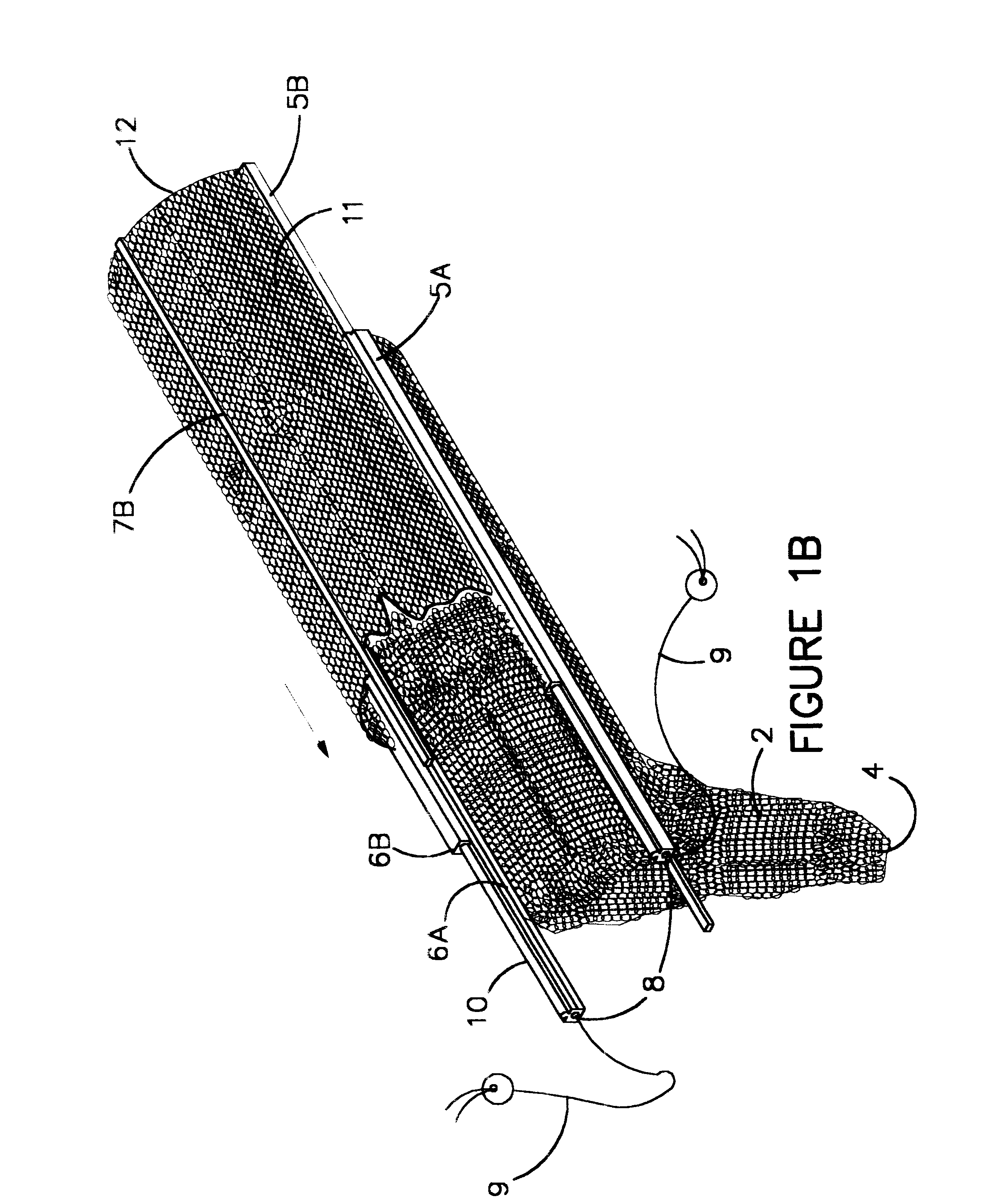
The invention comprises an elongated gripping member for assisting in the delivery of a fetus. Although the invention is described in terms of a human fetus, it is to be understood that the invention is equally applicable to non-human fetuses, and that it may be used in the delivery of the same. The elongated gripping member is made up of two separate sheets of loosely knitted fibers, preferably interlocking loops of polypropylene or nylon monofilarnent. Each sheet has a control end and a mouth end opposite the control end and a pair of insertion arms attached to each end of the sheets. Located between the insertion arms is a central insertion arm. The outside insertion arms of each sheet will slidingly engage one another. Thus, one half of the elongated gripping member may be inserted between the fetal head and the birth canal wall until the first half is properly placed around the fetal head. The second half of the elongated gripping member can then engage the first half and slide into position around the fetal head as well, thereby forming the elongated gripping member in place to engage the fetal head. A drawstring is provided in one half of the elongated gripping member to allow the mouth of the gripping member to tighten slightly before traction is initiated. This will prevent the elongated gripping member from slipping until compression gripping is initiated. Once compression gripping is commenced, tension on the drawstring will no longer be required. Additionally, pressure on the fetal head will be uniformly distributed by the elongated gripping member, thereby reducing the likelihood of injury to or deformation of the fetus.

Problems solved by technology

Several problems can arise in the use of the forceps.
However, properly placing the forceps can be difficult.
Particularly when the fetus is not properly positioned in a face down position in the birth canal, it can be difficult for the physician or other medical professional to locate the appropriate place on the fetus to position the forceps.
If these points are positioned improperly, pressure may be exerted on an eye, an ear, a temple, or other portions of the fetus's head which may be injured or deformed under such pressure, and in fact such injuries are all too common in forceps assisted deliveries.
However, positioning the device over the fetal head can be problematic.
When a delivery assistance device of any type is needed, the fetus has usually descended into the birth canal, but is not moving forward or is not moving forward fast enough.
Forcing a woven sock-like member between the fetal head and the birth canal walls can be difficult, as the loose edges of the elongated hollow sock-like member tend to gather at the boundary between the fetal head and the birth canal.
This can prevent the mouth of the delivery device from being placed completely over the fetus's head, making the initiation of axial gripping and traction difficult.

Method used


Image

  • Delivery assistance device
  • Delivery assistance device
  • Delivery assistance device

Examples


Embodiment Construction

The invention comprises an elongated first sheet 1 of loosely knitted fibers 2, preferably polypropylene monofilament or nylon. In a most preferred embodiment, fibers 2 are knitted together in series of interlocking loops as in a jersey knit. First sheet 1 has a mouth end 3 and a control end 4 opposite mouth end 3.

First sheet 1 extends between a first pair of insertion arms 5A, 6A which run from mouth end 3 toward control end 4. First insertion arms 5A and 6A should be thin and flexible in the dimensions transverse to the longitudinal dimension of first insertion arms 5A, 6A. However, first insertion arms 5A and 6A should be relatively stiff and strong in the dimension parallel to their longitudinal dimension. Preferably, first insertion arms 5A and 6A should be made of polystyrene.

A first central insertion arm 7A is positioned on first sheet 1 between first insertions arms 5A and 6A and also extends from mouth end 3 toward control end 4. Like first insertion arms 5A and 6A, first c...


PUM


Abstract

A device for assisting childbirth, preferably made of separate sheets of loosely knitted polypropylene loops. Each sheet has a control end, an opposite mouth end, and a pair of insertion arms attached to the edges of the sheets. The insertion arms of each sheet slidingly engage one another. Thus, one sheet may be inserted between the fetal head and the birth canal wall until it is properly placed about the fetal head. The second sheet can then engage the first sheet, sliding into position around the fetal head as well, thereby forming an elongated gripping member completely encircling the fetal head. A drawstring may be provided to assist in initiating traction. Thereafter, pulling on the gripping member will cause the loops to lengthen longitudinally and compress in their transverse dimension, causing the circumference of the gripping member to decrease and thereby grip the fetal head.

Description

1. Field of the InventionThe invention relates to obstetrical devices in general and to devices for assisting delivery of a human fetus in particular.2. Prior ArtThe principle delivery assistance device in the prior art are forceps. Forceps generally comprise a pair of opposed metal arms that are separately placed on either side of the fetus's head. Once the arms are in place, they are typically joined together at a centrally located hinge so that inward pressure on the control end of the two arms will result in the inward movement of the gripping ends of the arms against the fetus's head. Through this gripping, traction is obtained with the fetus's head, and by exerting lateral force against the forceps, the fetus may be extracted from the birth canal.Several problems can arise in the use of the forceps. When properly applied, the gripping end of the forceps are positioned over the upper jaw bone of the fetus in line with the ear. However, properly placing the forceps can be diffic...

Claims


Application Information

Patent Timeline
IPC IPC(8): A61B17/44A61B17/42
CPCA61B17/442
Inventor ALEXANDER, GARY
Owner MEDISYS TECH
Learn More