
Method and system for performing pseudo-random testing of an integrated circuit

a technology of integrated circuits and test chips, applied in the field of integrated circuit pseudo-random testing of integrated circuits, can solve the problems of increasing the complexity and density of circuit devices formed within a single chip, fewer i/o pins available, and several problems in regard to testing the proper operation of such integrated circuits

Inactive Publication Date: 2002-05-21
IBM CORP
View PDF3 Cites 66 Cited by
  • Summary
  • Abstract
  • Description
  • Claims
  • Application Information

AI Technical Summary

Benefits of technology

It is an advantage of the method and system that the design process of the integrated circuit proceeds with efficiency by correcting errors found in the subset thereof.

Problems solved by technology

As integrated circuit technology has advanced, the complexity and density of circuit devices formed within a single chip has increased dramatically.
Consequently, several problems have arisen with regard to testing proper operation of such integrated circuits.
For example, while the methodology for testing an integrated circuit (IC) may be relatively straight forward, most IC chips typically have far fewer I / O pins available to a circuit tester than are required to adequately test the IC and at the same time maintain the cost and functionality thereof.
In addition, most high end commercial testers can not provide a large number of I / Os at speed to adequately test the design.
A general shortcoming of the BIST testing methodology is the inability of the cycle of failure to be precisely detected at typical operating speeds of fast memories (e.g. greater than 200 MHz) because of the latency of data transmittal between the BIST circuit and the external tester.
In order to properly detect the cycle of failure after the BIST is halted, complex algorithms are typically employed which may take many hours or even days to determine the cycle of failure.
Further, no commercial external tester is available which can provide data patterns to a BIST circuit of an IC at speed for frequency ranges such as 1 GHz or greater and with a large number of channels (i.e. greater than 640 channels).
Thereby, even though the operational frequency of the chip may be 1 GHz, during testing, the frequency of operation would be limited by the latency of transfer between the external tester and the IC.
In addition, specialized I / O circuits which could communicate with the external tester to send and receive signals at this high rate of frequency would be necessary in an IC, adding circuit complexity to the IC for testing purposes.
Further limiting the testing of an IC, a BIST circuit cannot test data over continuous functional clock cycles because a pattern must be scanned in, a few functional clock cycles issued, and a result scanned out.
However, in designing for increased processor speeds, such as 1 GHz or greater, the volume of processor operations which can be performed per cycle is increased, thereby increasing the complexity of circuitry and the number of data paths within the functional units of the IC which need to be checked for errors.
Thereby, the width of test data vectors needed to properly test the functionality of such a processor is expanded to such a point that testing the processor with a BIST test would add an undesirable amount of circuitry.
In addition, BIST circuits do not have the advantage of providing test data subject to environmental conditions present within an integrated circuit such as noise, temperature, frequency limitations, etc.

Method used


Image

  • Method and system for performing pseudo-random testing of an integrated circuit
  • Method and system for performing pseudo-random testing of an integrated circuit
  • Method and system for performing pseudo-random testing of an integrated circuit

Examples


Embodiment Construction

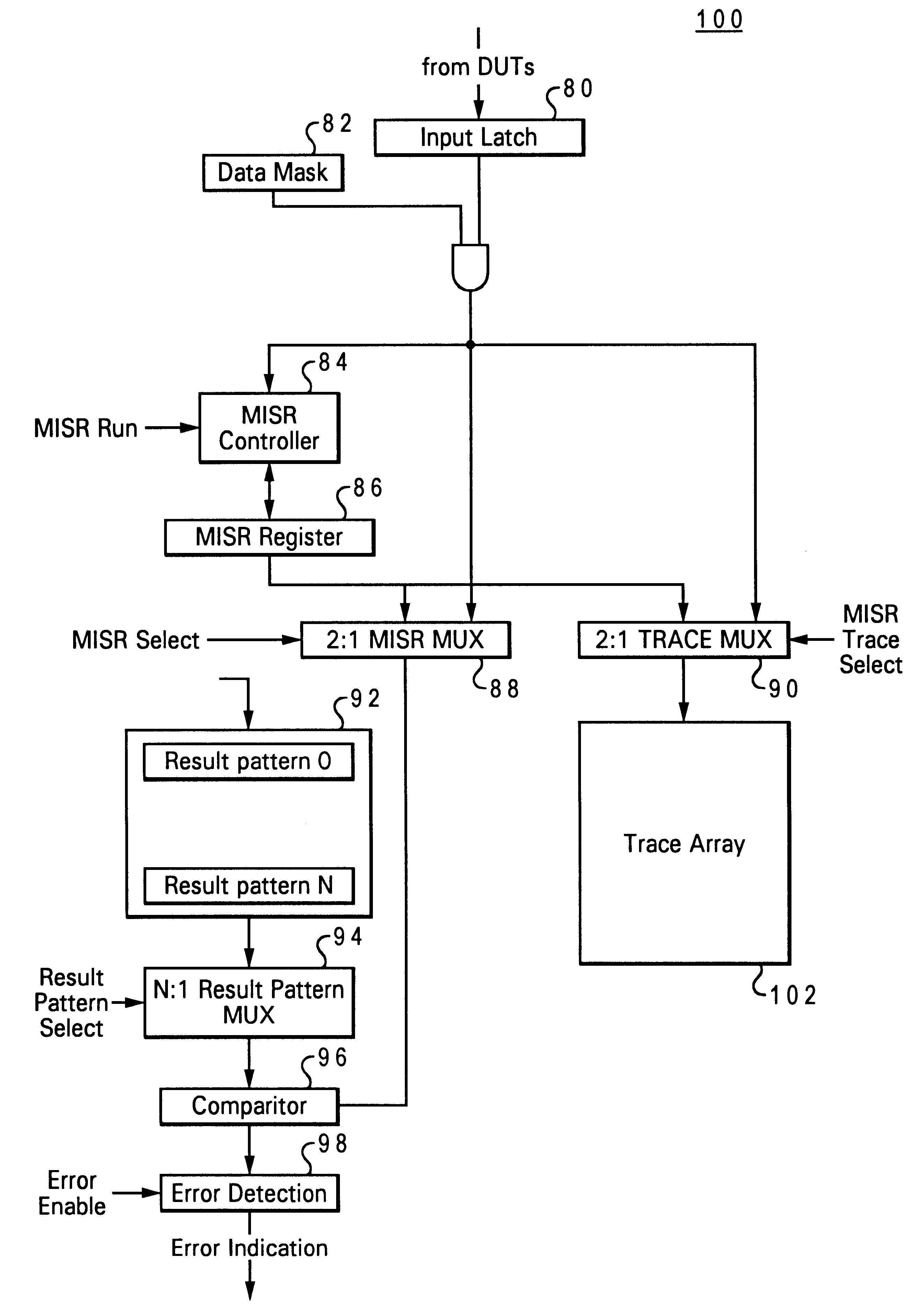
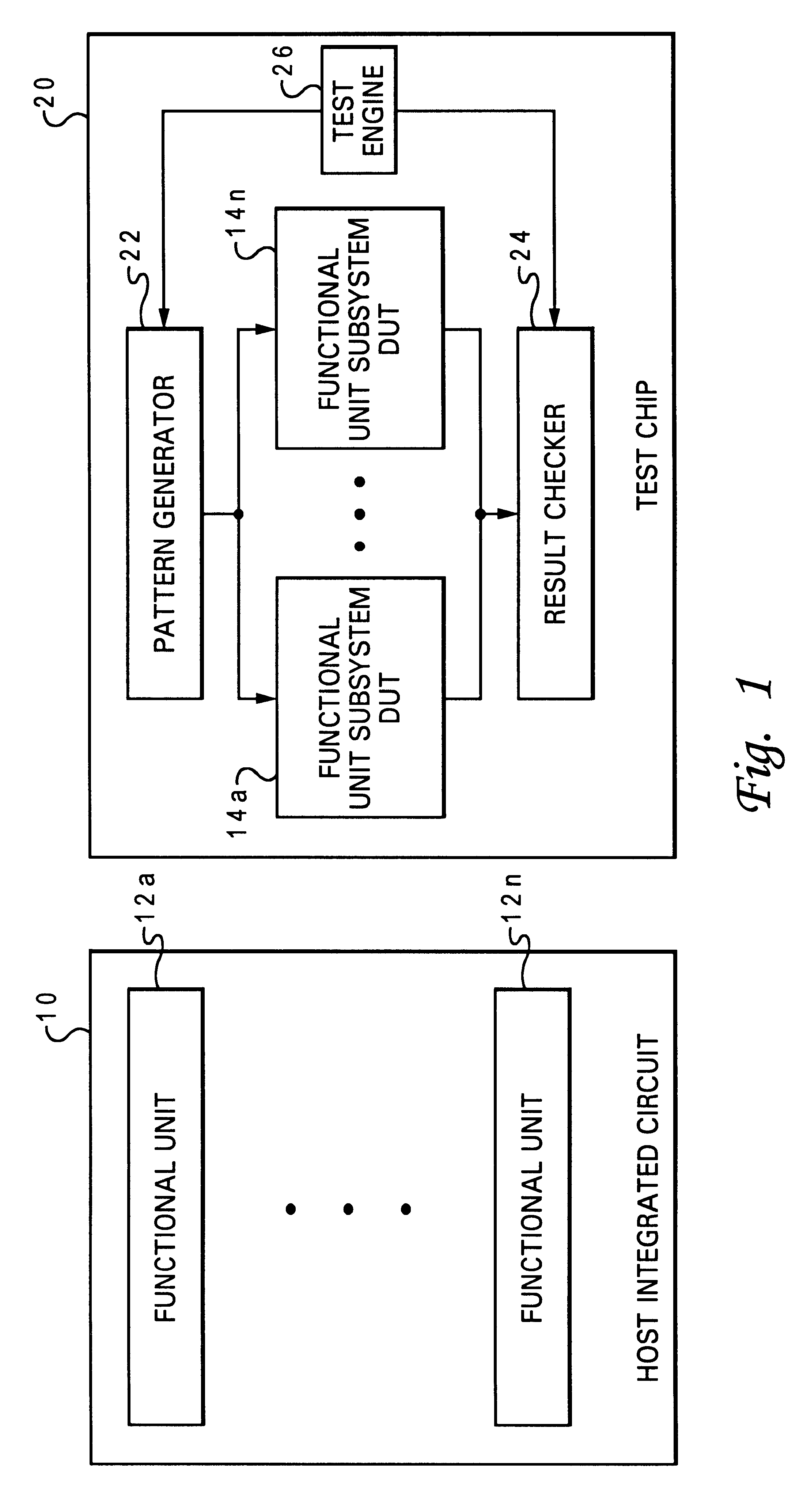
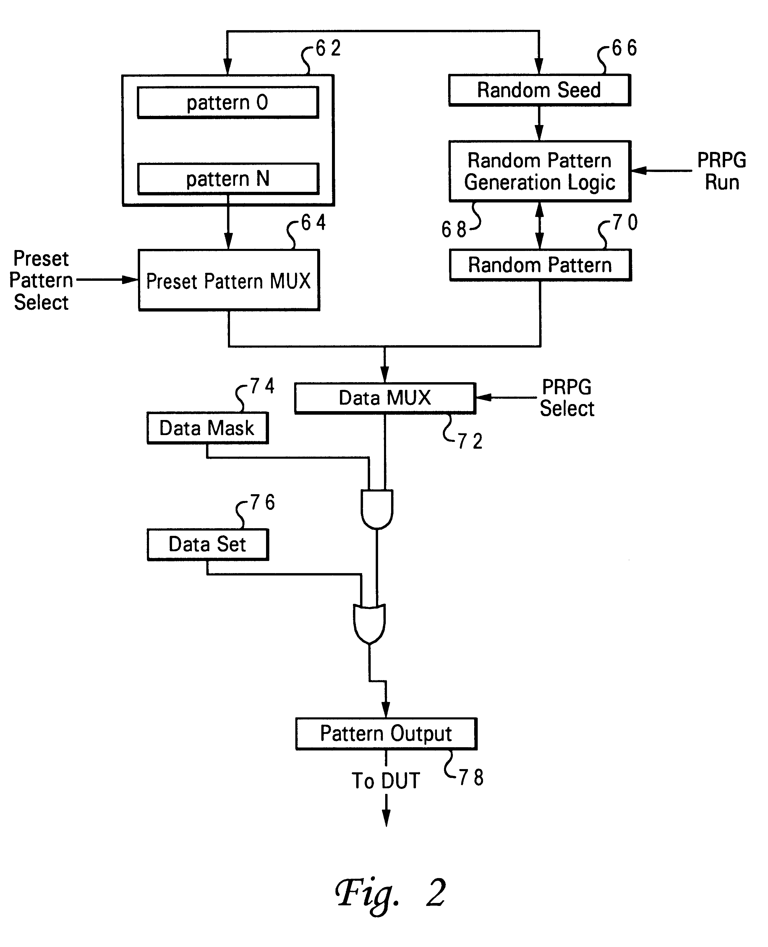
With reference now to the figures and in particular with reference to FIG. 1, there is depicted a block diagram representation of a host integrated circuit (IC) 10 and a test chip 20. Host IC 10 includes multiple functional units 12a-12n embedded within host IC 10 as is well known in the art. Typically, functional units 12a-12n are interconnected by a bus system (not shown) as needed for operation, supplied appropriate power (not shown) and synchronized in operation by a clock signal (not shown). Functional units 12a-12n may work together to perform processing functions. In addition, although not depicted, a production technology of the many available production technologies known in the art for manufacturing complex integrated circuits is employed for the manufacture of host IC 10. In particular, the production technology utilized may determine the effective speed at which a host IC 10 may be clocked to properly function. More particularly, with the advancement of production techno...


PUM


Abstract

A method and system for testing an integrated circuit. A test substrate is provided which is manufactured by the same particular production technology for which the integrated circuit is designed. A pattern generator for generating test data and a result checker for comparing output data are embedded on the test substrate. Isolated portions of circuitry of the integrated circuit are selectively embedded onto the test substrate. Test data from the pattern generator is applied to the isolated portions of circuitry under a first operating condition. The data output from the isolated portions of circuitry is selectively recorded into the result checker. The isolated portions of circuitry are then subjected to testing by applying test data from the pattern generator to the isolated portions of circuitry under a second operating condition. Errors in the isolated portions of circuitry are detected with the result checker by comparing data output from the isolated portions of circuitry with the selectively recorded data output, such that the integrated circuit is tested by subsets, independently of testing the integrated circuit in its entirety.

Description

1. Technical FieldThe present invention relates in general to an improved method and system for testing an integrated circuit and more particularly to a test chip for performing pseudo-random testing of a complex integrated circuit. Still more particularly, the present invention relates to a method and system for detecting errors in a subset of the complex integrated circuit which is embedded within a test chip, independent of the complex integrated circuit.2. Description of the Related ArtAs integrated circuit technology has advanced, the complexity and density of circuit devices formed within a single chip has increased dramatically. Consequently, several problems have arisen with regard to testing proper operation of such integrated circuits. For example, while the methodology for testing an integrated circuit (IC) may be relatively straight forward, most IC chips typically have far fewer I / O pins available to a circuit tester than are required to adequately test the IC and at th...

Claims


Application Information

Patent Timeline
Patent Type & Authority Patents(United States)
IPC IPC(8): G01R31/3183G01R31/28
CPCG01R31/318385G01R31/3183
Inventor ANDERSON, CARL J.FLOYD, MICHAEL STEPHENLEITNER, LARRY SCOTTMCCREDIE, BRADLEYREICK, KEVIN FRANKLINVARGUS, JENNIFER LANE
Owner IBM CORP
Learn More