
Load balancing and distributing switch-on control for a circuit breaker, an appliance, a device, or an apparatus

Inactive Publication Date: 2002-05-14
IBM CORP
View PDF18 Cites 40 Cited by
  • Summary
  • Abstract
  • Description
  • Claims
  • Application Information

AI Technical Summary

Problems solved by technology

These power consuming appliances, devices, and apparatuses all shut off during the power failure.
At the time that the power failure is rectified and power is restored, all appliances, devices, apparatuses begin to turn back on and start consuming power.
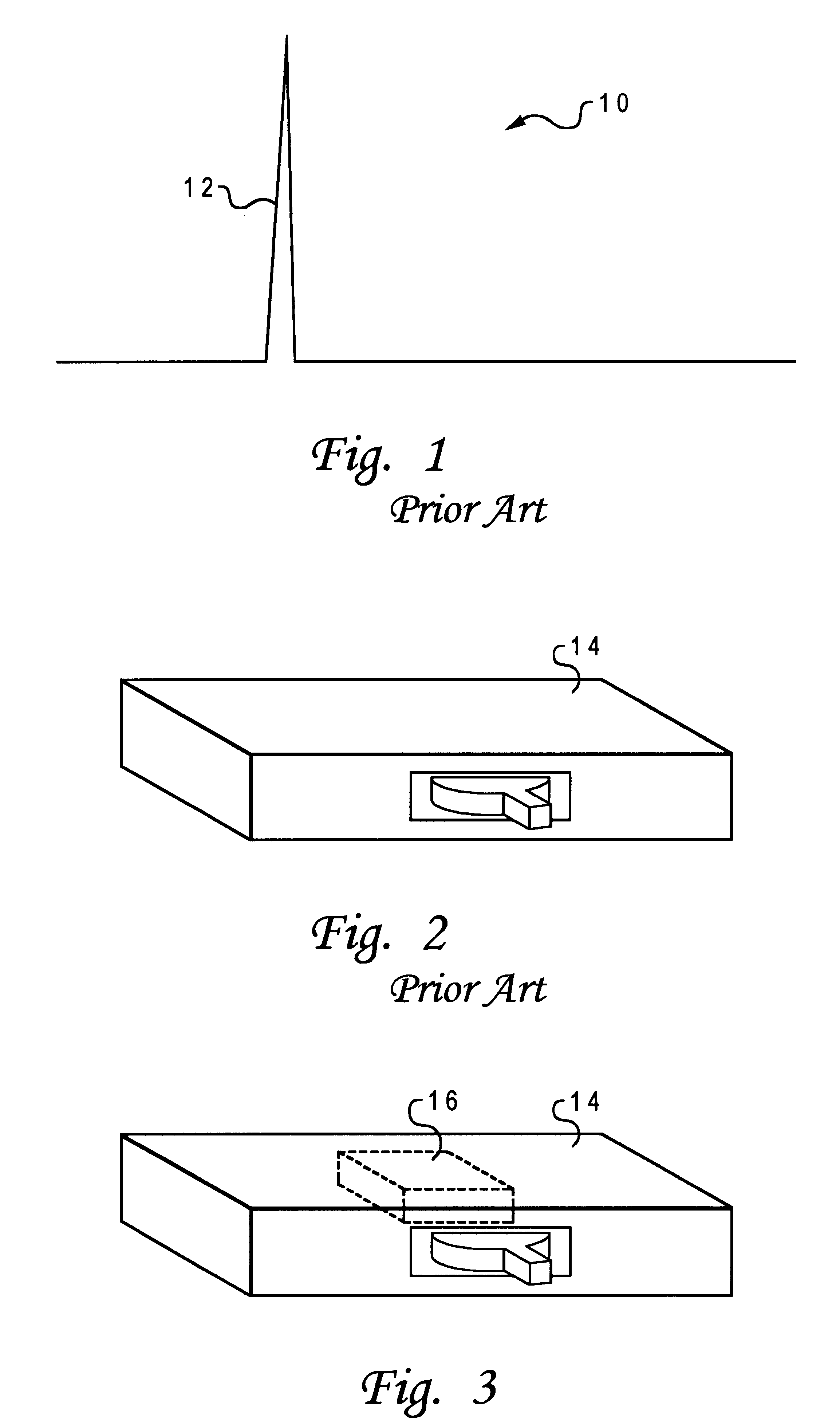
Thus, an extremely large load spike is created and generated during the time the various residences and commercial buildings are being restored with power wherein various appliances, devices, or apparatuses at the various residences and commercial buildings begin to again consume power.
One main problem when power is restored by a power company is that many appliances, devices, and apparatuses all begin to initiate and consume power at the same initial time.
Such a spike is or can be very problematic for a power company(ies).

Method used


Image

  • Load balancing and distributing switch-on control for a circuit breaker, an appliance, a device, or an apparatus
  • Load balancing and distributing switch-on control for a circuit breaker, an appliance, a device, or an apparatus
  • Load balancing and distributing switch-on control for a circuit breaker, an appliance, a device, or an apparatus

Examples


Embodiment Construction

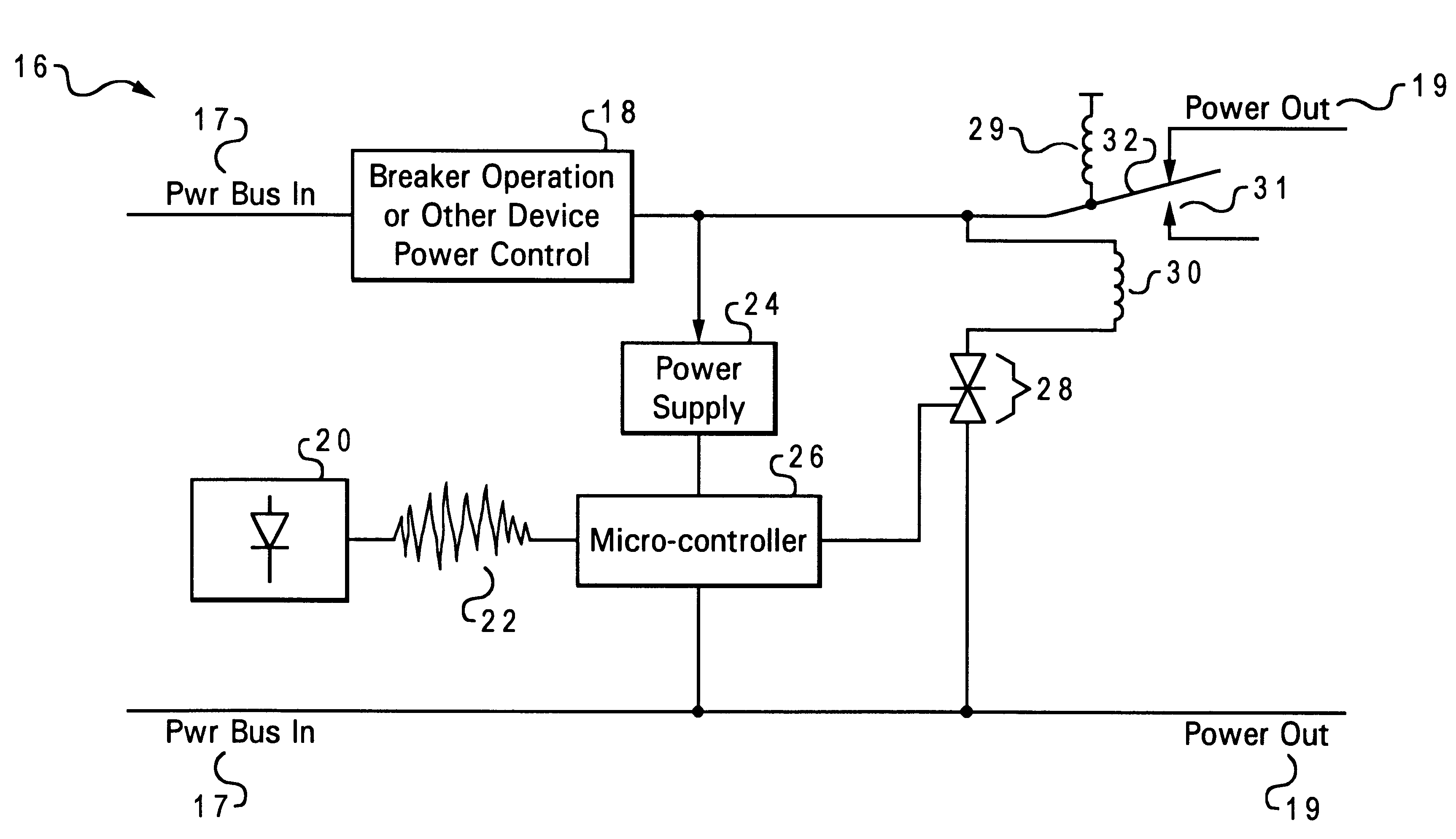
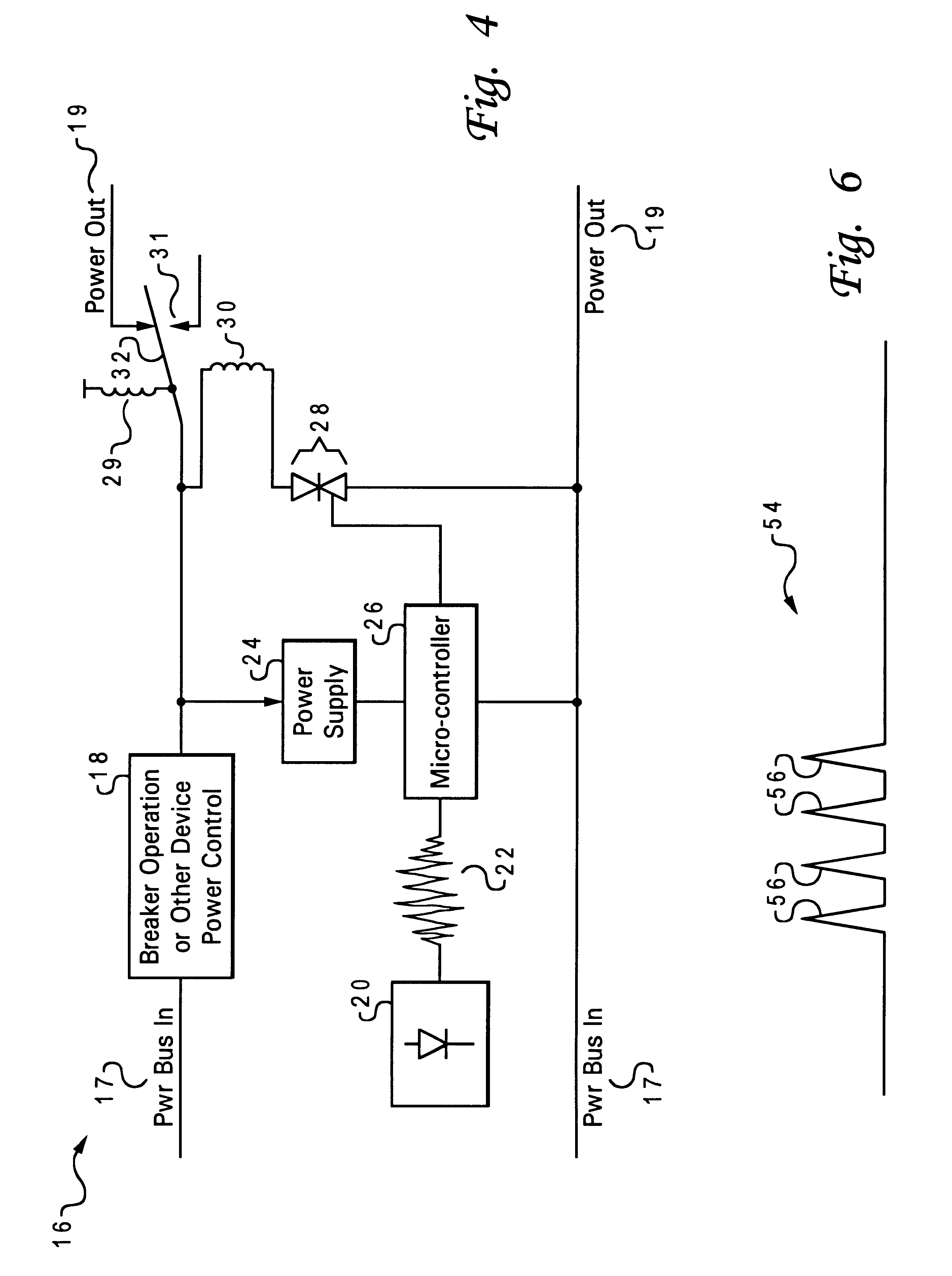
The present invention is a load balancing and distributing switch-on / turn-on control for a circuit breaker, an appliance, a device, or an apparatus wherein each switch-on device on a circuit breaker, appliance, device, or apparatus generates and provides a turn-on time delay up to a maximum turn-on time delay so that the turn-on times and respective loads after a power failure from all circuit breakers, appliances, devices, and / or apparatuses are distributed and / or balanced over a turn-on period. The present invention distributes and balances the load and consumption by various appliances, devices, and apparatuses at the time of initial power up after a power failure. The present invention also distributes the turn-on times of the various appliances, devices, and apparatuses at the initial power up time. The present invention further provides circuits for generating and providing various random power-up delay times for the appliances, devices, and apparatuses. The present invention ...


PUM


Abstract

The present invention is a load balancing and distributing switch-on / turn-on control for a circuit breaker, an appliance, a device, or an apparatus wherein each switch-on device on a circuit breaker, appliance, device, or apparatus generates and provides a turn-on time delay up to a maximum turn-on time delay so that the turn-on times and respective loads after a power failure from all circuit breakers, appliances, devices, and / or apparatuses are distributed and / or balanced over a turn-on period. The present invention distributes and balances the load and consumption by various appliances, devices, and apparatuses at the time of initial power up after a power failure. The present invention also distributes the turn-on times of the various appliances, devices, and apparatuses at the initial power up time. A circuit system and method for load balancing and distributing switch-on control of an operating device. A micro-controller is able to couple to the operating device and to a power-in bus for receiving power from a power source. A relay switch system is coupled to the micro-controller for controlling the power from the power-in bus. The relay switch system is able to couple to a power-out bus to control the power to the operating device. The micro-controller generates a power-up delay time through which the micro-controller must wait and control the relay switch system to hold the power to the power-out bus before the relay switch is released to supply the power to the power-out bus for operation of the operating device.

Description

1. Technical FieldThe present invention relates in general to a switch-on control circuit system and method and, in particular, to a load balancing and distributing switch-on control for a circuit breaker, an appliance, a device, or an apparatus wherein each switch-on device on a circuit breaker, appliance, device, or apparatus generates and provides a turn-on time delay up to a maximum turn-on time delay so that the turn-on times and respective loads after a power failure from all circuit breakers, appliances, devices, and / or apparatuses are distributed and / or balanced over a turn-on period.2. Description of the Related ArtWhen a power failure occurs, power to circuit breakers at residences and commercial buildings and to appliances, devices, or apparatuses is cut off and ceases to exist. These power consuming appliances, devices, and apparatuses all shut off during the power failure. At the time that the power failure is rectified and power is restored, all appliances, devices, ap...

Claims


Application Information

Patent Timeline
IPC IPC(8): H02H11/00H02H3/24
CPCH02H11/00H02H3/24
Inventor BERSTIS, VIKTORSSMITH, JOEL LESLIE
Owner IBM CORP
Learn More