
Optical waveguide circuit, and method for compensating the light transmission wavelength

a technology of optical waveguides and waveguides, applied in the direction of optical waveguide light guides, instruments, optics, etc., can solve the problems of less reliability of control for which the temperature holding mechanism is provided in compensation of the center wavelength of light transmission, increase the cost of the arrayed waveguide diffraction grating module in which these elements are provided, and increase the module size. cost

Inactive Publication Date: 2002-04-23
FURUKAWA ELECTRIC CO LTD
View PDF17 Cites 32 Cited by
  • Summary
  • Abstract
  • Description
  • Claims
  • Application Information

AI Technical Summary

Benefits of technology

to provide an optical waveguide circuit which does not need any large-sized apparatus, is capable of compensating a temperature dependency of the center wavelength of light transmissions of an optical waveguide circuit such as an arrayed waveguide diffraction grating, and a shift from a predetermined set wavelength with ease and at a low cost, and a method for compensating the light transmission wavelengths.
FIG. 19 is an explanatory view showing one example of a conventionally proposed arrayed waveguide diffraction grating to reduce the temperature dependency of the light transmission characteristics.

Problems solved by technology

Accordingly, an arrayed waveguide diffraction grating module in which these elements are provided becomes very expensive in cost, and further the module size thereof is also increased.
Therefore, control for which the temperature holding mechanism is provided has less reliability in compensation of the center wavelength of transmission of lights.
Accordingly, it is very difficult to produce the arrayed waveguide diffraction grating 11, and mass production thereof is also difficult, whereby the cost of such an arrayed waveguide diffraction grating 11 is increased.
Further, in such an arrayed waveguide diffraction grating 11, even though the waveguide of the arrayed waveguide diffraction grating 11 and the groove 13 are accurately formed, it is unavoidable that a difference in production occurs.
However, in the case of using this method, it is difficult to control the irradiation intensity and time of an ultraviolet ray, and the ultraviolet ray irradiation apparatus is large-sized and becomes expensive.

Method used


Image

  • Optical waveguide circuit, and method for compensating the light transmission wavelength
  • Optical waveguide circuit, and method for compensating the light transmission wavelength
  • Optical waveguide circuit, and method for compensating the light transmission wavelength

Examples


Embodiment Construction

To describe the invention in further detail, a description is given of preferred embodiments with reference to the accompanying drawings. The description of the preferred embodiments, parts which are identical to those of the prior art example are given the same reference numbers, and overlapping description thereof is omitted.

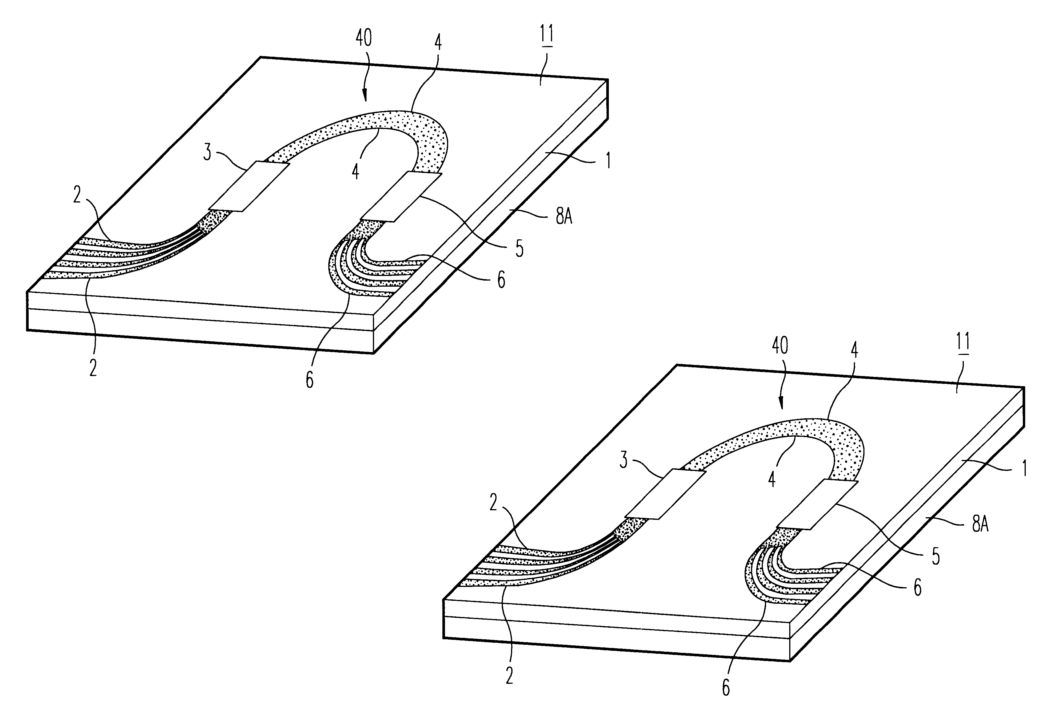
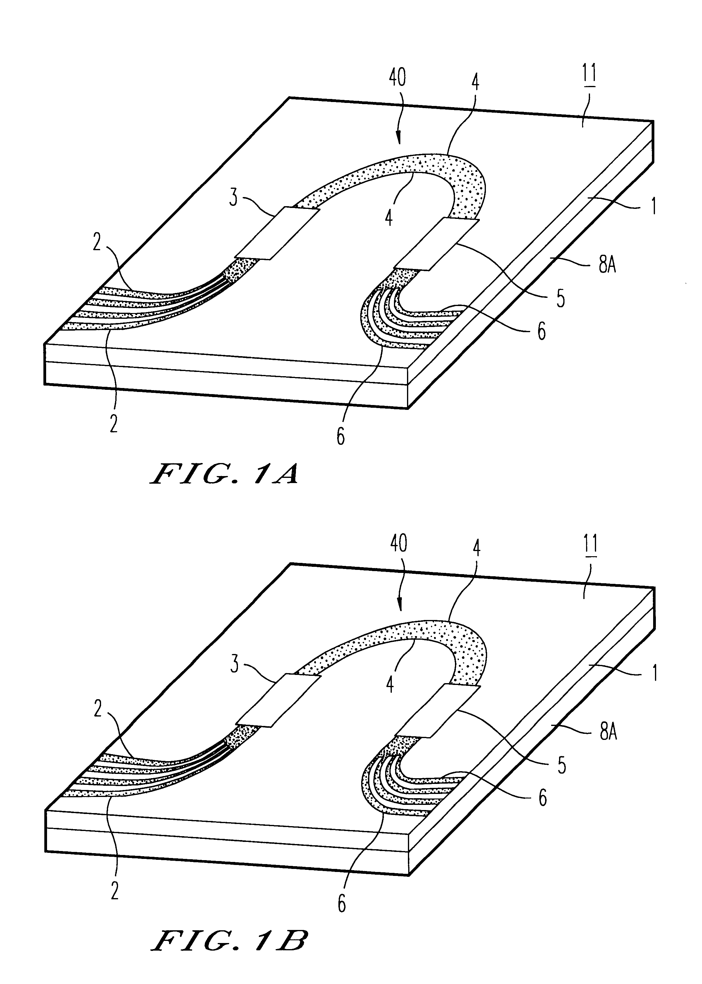
In FIG. 1, a first preferred embodiment of an arrayed waveguide diffraction grating according to the invention is illustrated. The optical waveguide circuit is an arrayed waveguide diffraction grating 11. Also, in (a) of the same drawing, a state of the arrayed waveguide diffraction grating 11 at a normal temperature (for example 25.degree. C.) is illustrated. In (b) of the same drawing, a state of the arrayed waveguide diffraction grating 11 at a higher temperature than 25.degree. C. is illustrated.

The arrayed waveguide diffraction grating 11 forms, on a single silicon crystal substrate, a waveguide construction which is similar to the waveguide construction ...


PUM


Abstract

A plate-shaped member (8a) whose linear expansion coefficient is larger than that of a substrate (1) is provided on the rear side of the substrate (1) of an arrayed waveguide diffraction grating (11) which divides, by a diffraction effect of an array waveguide (40), lights of a plurality of wavelengths from those having a plurality of wavelengths different from each other, which are inputted from an optical input waveguide (2), and outputs these lights from the respective optical output waveguides (6). A light transmission feature of the respective output lights includes a light transmission feature for causing lights to be transmitted, centering around the center wavelengths of light transmission, which are different from each other, wherein the center wavelengths of light transmission shifts to the long wavelength side by a temperature rise.

Description

The present invention relates to an optical waveguide circuit, which is used as a wavelength filter and an optical wavelength synthesizing and dividing device, etc., used for light transmissions, and a method for compensating the light transmission wavelength. In particular, the invention relates to an optical waveguide circuit which compensates for a fluctuation in temperature of the light transmission wavelength, and a method for compensating the light transmission wavelength thereof.BACKGROUND OF THE ARTRecently, as a method to remarkably increase a transmission capacity in optical transmissions, studies and research have actively been carried out with respect to optical wavelength division multiplexing transmissions, and actual uses thereof have been commenced. The optical wavelength division multiplexing transmission is, for example, to transmit a plurality of lights having different wavelengths from each other while multiplexing the same. In such a system for optical wavelengt...

Claims


Application Information

Patent Timeline
IPC IPC(8): G02B6/34G02B6/12
CPCG02B6/1203
Inventor SAITO, TSUNETOSHIOHTA, TOSHIHIKO
Owner FURUKAWA ELECTRIC CO LTD
Learn More