
Current limiting device with conductive composite material and method of manufacturing the conductive composite material and the current limiting device

a technology of current limiting device and conductive composite material, which is applied in the direction of non-conductive material with dispersed conductive material, non-metal conductor, conductor, etc., can solve the problems of thermosetting monomers not being able to meet the requirements of thermosetting monomers, thermosetting polymers are often brittle, and thermosetting polymers undergo substantial shrinkag

Inactive Publication Date: 2002-04-16
GENERAL ELECTRIC CO
View PDF50 Cites 24 Cited by
  • Summary
  • Abstract
  • Description
  • Claims
  • Application Information

AI Technical Summary

Problems solved by technology

However, thermosetting polymers are often brittle.
Thus, thermosetting monomers will not withstand a switching event or high current event without catastrophically fracturing, which of course is undesirable.
Additionally, thermosetting polymers undergo substantial shrinkage during cure that can alter the microstructure of the material.
Accordingly, for some applications it is not desirable to use a thermosetting polymer to control at least the concentration, morphology, and state of aggregation of the conductive filler material within the polymer matrix in a current limiting device.

Method used


Image

  • Current limiting device with conductive composite material and method of manufacturing the conductive composite material and the current limiting device
  • Current limiting device with conductive composite material and method of manufacturing the conductive composite material and the current limiting device
  • Current limiting device with conductive composite material and method of manufacturing the conductive composite material and the current limiting device

Examples


Embodiment Construction

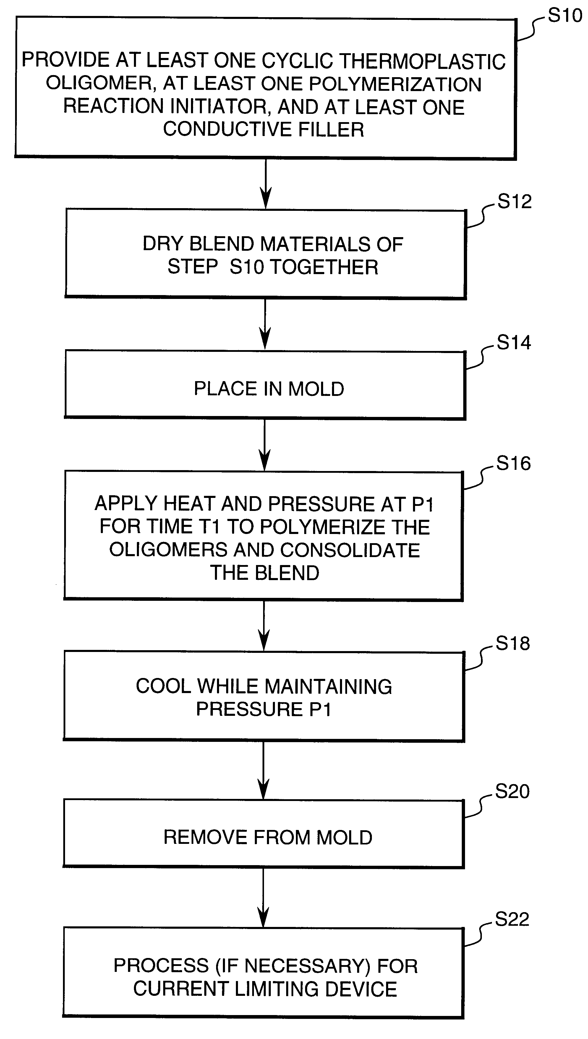
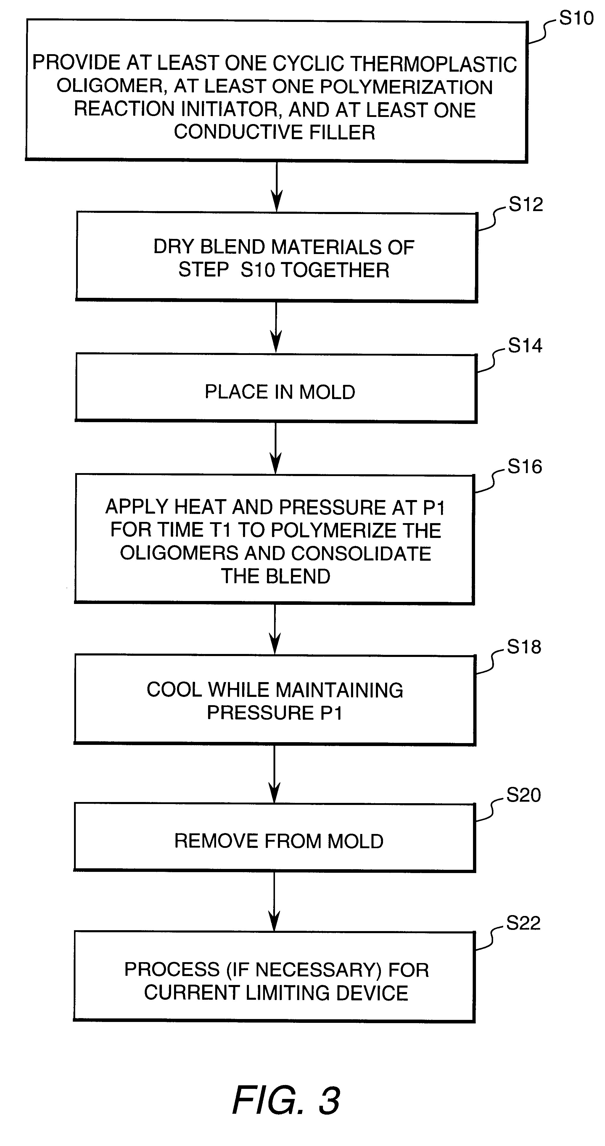
A current limiting device, as embodied by the invention, comprises an electrically conductive composite material positioned between electrodes, so that there is an inhomogeneous distribution of resistance throughout the current limiting device. The electrically conductive composite material comprises at least a conductive filler and at least one organic, preferably polymeric, binder matrix. The current limiting device, as embodied by the invention, further comprises means for exerting compressive pressure on the electrically conductive composite material of the current limiting device.

The current limiting device, as illustrated in FIG. 1, is embodied as a high current multiple use fast-acting current limiting device 1. In FIG. 1, the current limiting device 1, as embodied by the invention, comprises electrodes 3 and an electrically conductive composite material 5 with inhomogeneous distributions 7 of resistance structure under compressive pressure P. The electrically conductive comp...


PUM


Abstract

A current limiting device comprises at least two electrodes; an electrically conducting composite material between the electrodes; interfaces between the electrodes and electrically conducting composite material; an inhomogeneous distribution of resistance at the interfaces whereby, during a high current event, adiabatic resistive heating at the interfaces causes rapid thermal expansion and vaporization and at least a partial physical separation at the interfaces; and a structure for exerting compressive pressure on the electrically conducting composite material, wherein the electrically conducting composite material comprises at least one polymer matrix and at least one conductive filler.

Description

1. Field of the InventionThis invention relates to current limiting devices for general circuit protection including electrical distribution and motor control applications. In particular, the invention relates to current limiting devices that are capable of limiting the current in a circuit when a short circuit event or high current condition occurs, a conductive composite material used therein, and a method of manufacture of a conductive composite material.2. Description of Related ArtThere are numerous devices that are capable of limiting the current in a circuit when a high current condition occurs. One known limiting device includes a filled polymer material that exhibits what is commonly referred to as a PTCR (positive-temperature coefficient of resistance) or PTC effect. U.S. Pat. No. 5,382,938, U.S. Pat. No. 5,313,184, and European Published Patent Application No. 0,640,995 A1 each describes electrical devices relying on PTC behavior. The unique attribute of the PTCR or PTC e...

Claims


Application Information

Patent Timeline
IPC IPC(8): H01C7/102
CPCH01C7/102
Inventor DUGGAL, ANIL RAJSALEM, ANDREW JAYLEVINSON, LIONEL MONTYTODT, MICHAEL LESLIE
Owner GENERAL ELECTRIC CO
Learn More