
Electrical cable having a self-sealing agent and method for preventing water from contacting the conductor

a technology of self-sealing agent and conductor, which is applied in the direction of insulated conductors, cables, conductors, etc., can solve the problems of voids in the sealant, failure to meet the technical and/or economic success, and inability to introduce a sealant into such spaces

Inactive Publication Date: 2002-03-19
PRYSMIAN CAVI E SISTEMI ENERGIA
View PDF11 Cites 37 Cited by
  • Summary
  • Abstract
  • Description
  • Claims
  • Application Information

AI Technical Summary

Problems solved by technology

However, it has been found that the mere introduction of a sealant into such spaces is not entirely satisfactory.
Attempts to prevent moisture from reaching the conductor, such as using water swellable material, have not met with technical and / or economic success.
For example, voids may be formed in the sealant during the application thereof or may be formed if the cable is accidentally punctured.
Any such spaces or voids form locations for the ingress of moisture which can lead to corrosion of the conductor and conventional sealants used in the cables cannot eliminate such voids.
The drawback to this method is that even though some deformation of the individual wires does take place, and some of the interstitial spacing is filled, there is still the possibility of cable insulation damage through which moisture can enter the cable and contact the conductor.
The problems encountered in applying such a filling substance revolve around precise metering of the material into the interstitial spaces as the stranded conductor is being formed.
If too much material is extruded into the conductor, the outer insulation will not fit properly.
Another drawback to this method of applying a moisture blocking material is that an extrusion head and an extrusion pump for applying the material is required for every individual layer of wires used to form the conductor.
The problems described above regarding the regulation of the volume of material applied through an extrusion head are multiplied every time an additional extrusion pump and extrusion head is required within the conductor manufacturing system.
Prior art efforts to manufacture an acceptable moisture blocked conductor revolved around methods for uniform application of the moisture blocking material to the conductor, but did not solve the problems created by handling and installation damage.
The disadvantages experienced here involve the practice of stranding the conductor beneath the surface of an elevated temperature moisture block pool.
No access, either visual or mechanical, to the conductor manufacturing process is practical.
The disadvantages here comprise a complex manufacturing line whereby moisture blocking material is applied at many different locations, each having to be meticulously monitored and controlled in order for a proper conductor construction to be obtained.
It can be readily seen from the above referenced methods and apparatuses that moisture blocked conductors are known and it can also be recognized that there are major problems concerning the elimination of moisture contacting the conductor as a result of handling and installation of a cable.

Method used


Image

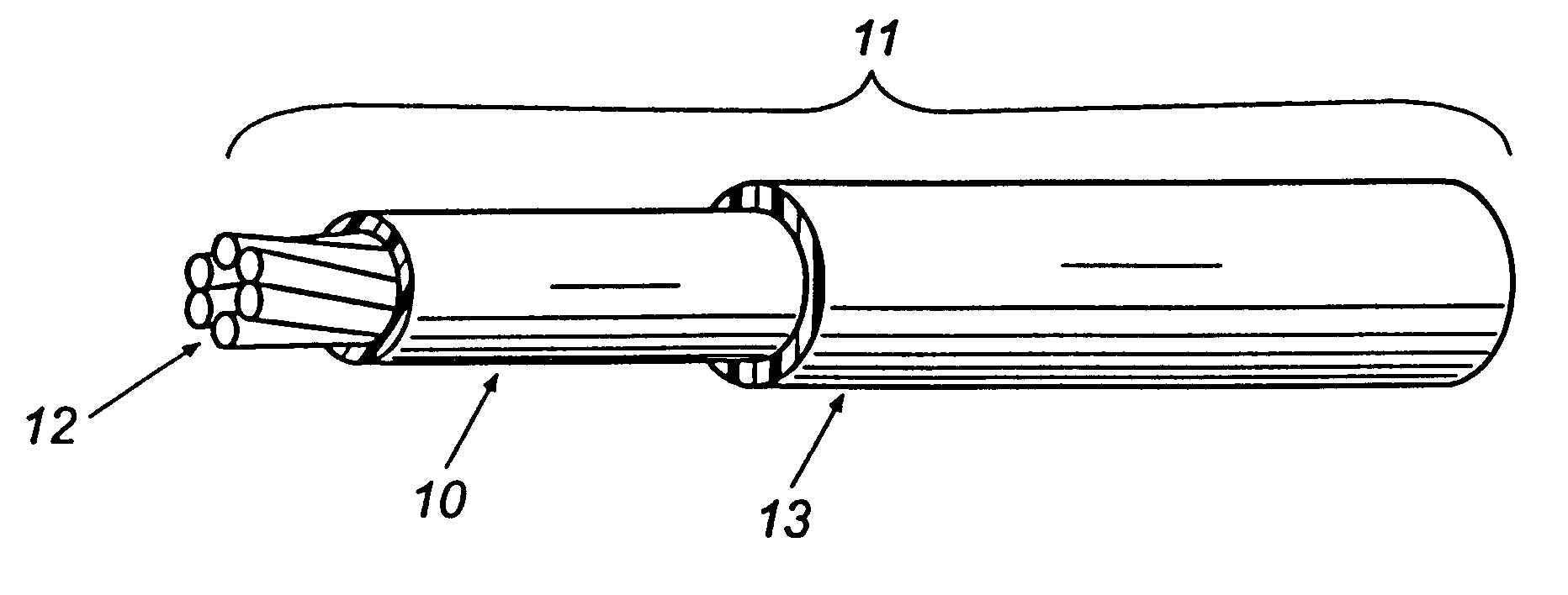
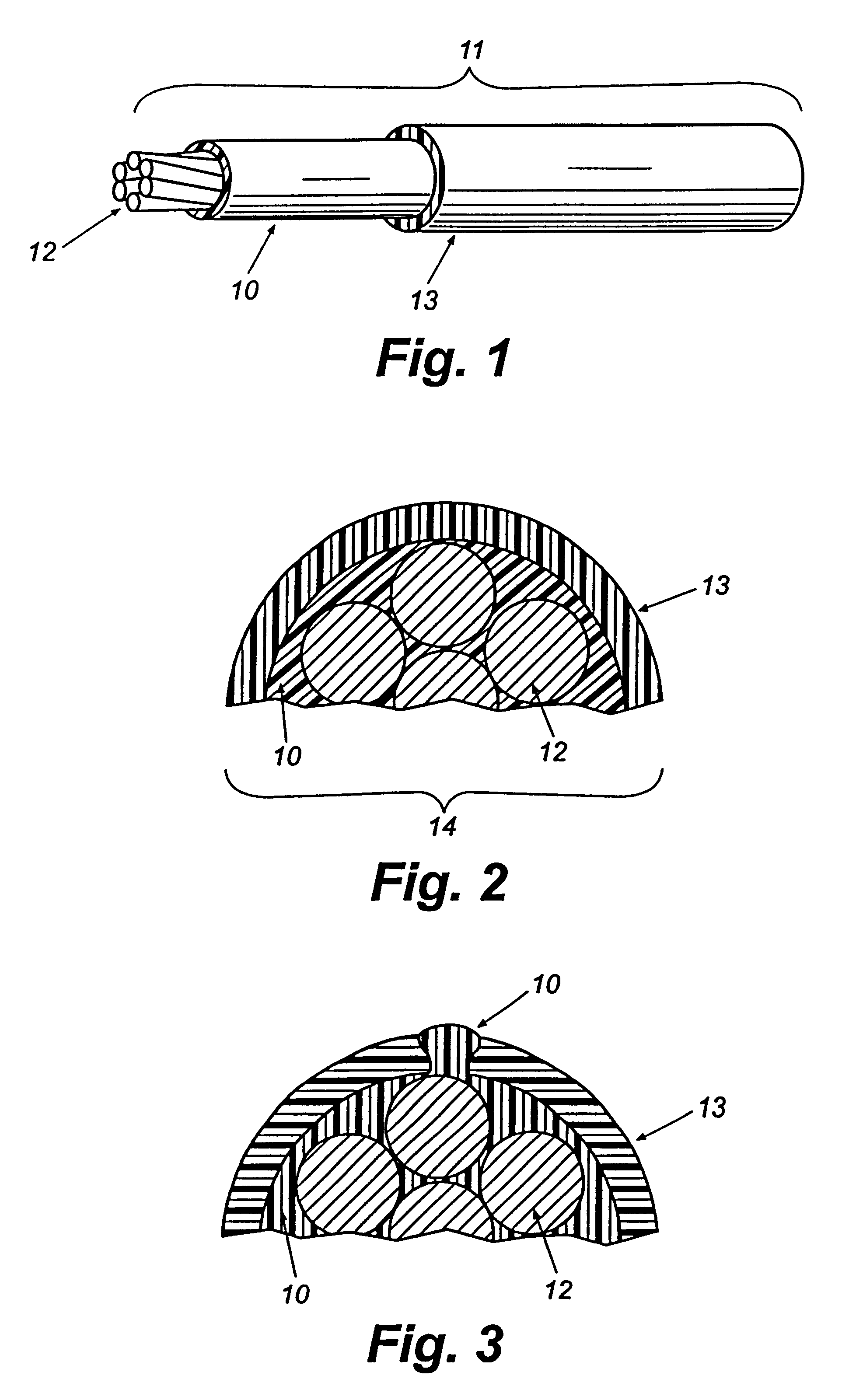
  • Electrical cable having a self-sealing agent and method for preventing water from contacting the conductor
  • Electrical cable having a self-sealing agent and method for preventing water from contacting the conductor

Examples


example 1

Defects which exposed the conductor were made in the insulation layer of two 600 V cable samples. On one of the cable samples, a layer of polyisobutene polymer had been applied to the surface of the conductor. The other cable sample did not have the polyisobutene layer. Both cable samples were placed inside separate 1 liter glass beakers containing tap water. Each cable sample was energized at 110 V to ground with AC current. The sample which did not have the polyisobutene layer exhibited severe corrosion overnight. The sample containing the polyisobutene layer exhibited no corrosion after being energized and submerged for 4 weeks in tap water in the glass beaker.

Although preferred embodiments of the present invention have been described and illustrated, it will be apparent to those skilled in the art that various modifications may be made without departing from the principles of the invention.

example 2

The conductors from seven 600 V cable samples approximately 12 inches in length were coated with the polyisobutylene. A defect was made in the middle of each sample which exposed the conductor. Three untreated cables (without polyisobutylene) were similarly damaged to expose the conductor. Each of the cable samples was then placed inside a laboratory rectangular soil box, across and through the long sides of the box, which was then filled with soil. Each sample was energized at 110 V to ground. The soil box was periodically watered to insure that the conditions leading to AC corrosion were present. Measurements of leakage current were taken to monitor the effect of the polyisobutylene layer on preventing corrosion. Periodically, the ability of each sample to carry 20 amps AC current was tested. Over a period of 2 months, all of the untreated cables showed increasing levels of current leakage, indicating progressive corrosion. The ability of the untreated samples to carry current det...


PUM

PropertyMeasurementUnit
Angleaaaaaaaaaa
Massaaaaaaaaaa
Thicknessaaaaaaaaaa

Abstract

An electrical cable with a stranded central conductor encircled by insulation including a material which provides self-sealing properties to the cable present at least between the adjacent edges of the stranded conductor and the insulation. Preferably, the material is a polymeric material which is flowable at a temperature at least as low as 25° C. and has a 100 gram needle penetration value greater than 100 tenths of a millimeter at 25° C.

Description

Insulated solid and stranded electrical cables are well known in the art. Generally stranded cables include a central stranded conductor with a protecting insulation jacket disposed around the conductor.The most frequent cause of failure of directly buried aluminum secondary cables is a cut or puncture in the insulation inflicted during or after installation. This leads to alternating current corrosion of the aluminum and finally to an open circuit. When a conductor is exposed to wet soil, upon damage, leakage current may flow, and cause localized electrochemical conversion of aluminum to hydrated aluminum oxide and eventually to an open circuit of the conductor.In the U.S., thousands of such instances occur annually and the repair (location, excavation, repair, and replacement) can be very costly. As a result of the failures and in response to this problem, a tougher insulation system was introduced and became an industry standard. The tougher cable is described as "ruggedized," an...

Claims


Application Information

Patent Timeline
IPC IPC(8): H01B7/282H01B7/17
CPCH01B7/2825Y02A30/14
Inventor REECE, DAVIDWALLER, JONATHANWARE, NICKSASSE, PHILIP
Owner PRYSMIAN CAVI E SISTEMI ENERGIA
Learn More