Eureka AIR delivers breakthrough ideas for toughest innovation challenges, trusted by R&D personnel around the world.

Vehicle transmission apparatus having a valve for controlling cornering behavior

a transmission apparatus and valve technology, applied in mechanical devices, belts/chains/gearrings, gear control, etc., can solve the problems of not being able to generate different traction forces for the inner wheel and the outer wheel, and not being able to obtain a particular traction force on a given one, so as to improve the behavior of the vehicle

Inactive Publication Date: 2002-03-12
POCLAIN HYDRAULICS IND
View PDF5 Cites 34 Cited by
  • Summary
  • Abstract
  • Description
  • Claims
  • Application Information

AI Technical Summary

Benefits of technology

An object of the present invention is to remedy the above-mentioned drawbacks so as to improve the behavior of the vehicle in particular during turning, by making it possible, during turning, for the inner and outer wheels to be driven at different speeds while being capable of delivering traction forces that are also different.
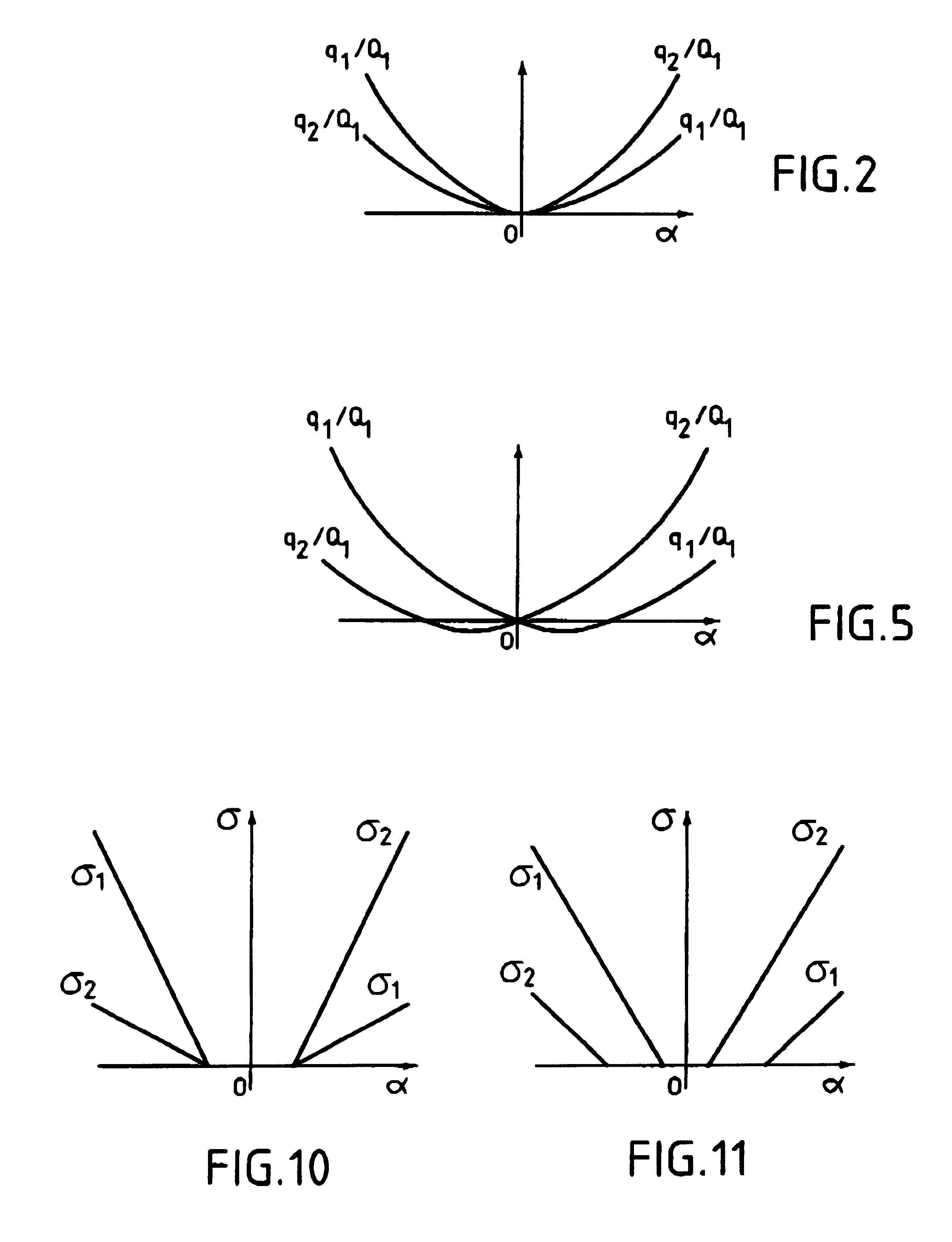
In particular, the flow sections in the first and second right branches are chosen to be different from each other, and the flow sections in the first and second left branches are also chosen to be different from each other. In this way, when the selection valve is in its left-turn position or in its right-turn position, the pressures in the two series pipes can be different, which makes it possible, while turning, to guarantee that the torques transferred, and thus the traction forces, are different between the various wheels of the vehicle, in particular between one or more inner wheels and one or more outer wheels.
This constitutes a simple manner of setting the various flow sections of the selection valve for a vehicle whose behavior during right and left turns is substantially symmetrical.
The smaller the radius of curvature of the turn, the greater the extent to which the curves described by the outer wheels differ from the curves described by the inner wheels, so that the difference in speed necessary between the outer wheels and the inner wheels is greater.
It is thus advantageous to cause the valve to go progressively between its configurations as a function of the directions of the steerable displacement members. Generally, for a turn of very large radius of curvature, the valve can be displaced a little towards its left or right turn configuration so as to give rise to only a small difference in flow section between the first and second right or left branches. In contrast, in a turn having a small radius of curvature, the valve can be displaced to a much larger extent into its right or left turn configuration so as to give rise to a much larger difference in flow section between the first and second right or left branches.

Problems solved by technology

Unfortunately, with the apparatus of the above-mentioned documents, during turning, the two series pipes are connected via the same path to one of the ports of the pump.
Therefore, with apparatus of the above-mentioned type, when the valve for decoupling the motors during turning is activated, it is not possible to obtain a particular traction force on a given one of the wheels of the vehicle, even though it is necessary to do so.
Furthermore, there is a risk of wheel spin in this situation.
Unfortunately, it is not possible for the motors driving the inner and the outer wheels to deliver different torque values, so that it is not possible to generate different traction forces for the inner wheel and for the outer wheel.

Method used


Image

  • Vehicle transmission apparatus having a valve for controlling cornering behavior
  • Vehicle transmission apparatus having a valve for controlling cornering behavior
  • Vehicle transmission apparatus having a valve for controlling cornering behavior

Examples


Embodiment Construction

FIG. 1 shows the positions of the four drivable wheels 1, 2, 3, and 4 of a vehicle turning a corner whose radius of curvature is R. In the example shown, the two front wheels 1 and 2 are steerable. To start turning, the driver actuates the steering of the vehicle so as to turn the wheels 1 and 2. These wheels are thus inclined so as to be placed on the curves whose radii of curvature are respectively R.sub.1 and R.sub.2.

The rear wheels 3 and 4 are non-steerable. During the turning, they find themselves on the curves whose radii of curvature are respectively R.sub.3 and R.sub.4. It is thus possible to plot the steering diagram of the vehicle, i.e. the curves defined by the variations in the radii of curvature R.sub.1 to R.sub.4 as a function of the radius R, or rather as a function of the angle .alpha. that represents the inclination of the steerable wheel on the outside of the turn. Each of the wheels of the vehicle then has distance to cover that depends on the radius of curvature ...


PUM


Abstract

Hydrostatic transmission apparatus for a vehicle having drivable front and rear wheels coupled to front and rear hydraulic motors. A group of motors comprises at least two motors coupled respectively to two wheels situated on either side of the vehicle. The other group of motors comprises at least one motor driving a wheel. The two motors of the first group are dual-capacity motors, each comprising a first elementary motor connected to the pump in parallel with a motor of the second group, and a second elementary motor which is connected in series with said motor of the second group. Two series pipes are thus defined. The apparatus comprises a selection valve connected to the two series pipes and to a port of the pump. This valve can take up a straight-ahead configuration in which the series pipes are isolated from the port of the pump, as well as a left-turn configuration and a right-turn configuration in which the series pipes are connected to said port. The flow sections in at least some of the path branches between the series pipes and said port of the pump are different.

Description

The present invention relates to hydrostatic transmission apparatus for a vehicle having a front group of displacement members and a rear group of displacement members, the displacement member(s) of one of said groups being steerable members.The apparatus comprises a transmission circuit which includes a pump, and hydraulic motors both in a front group of motors and in a rear group of motors, for driving the displacement members in the front and rear groups. A first one of the front and rear groups of motors comprises at least two motors in which two displacement members situated on either side of the vehicle are respectively coupled, while the second group of motors comprises at least one motor to which at least one displacement member is coupled, the two motors of the first group of motors being dual-capacity motors each having two distinct operating cylinder capacities which correspond respectively to a first elementary motor and to a second elementary motor, the first elementary...

Claims


Application Information

Patent Timeline
IPC IPC(8): B60K17/34B60K23/08B60K17/356B60K17/10
CPCB60K17/10F16H61/456B60K23/0808B60K17/356
Inventor COUSIN, JEAN-CLAUDEMARTIN, LOUIS
Owner POCLAIN HYDRAULICS IND
Why Eureka
Eureka Blog
Learn More