Apparatus for filtering and degassing body fluids, in particular blood filter

a technology of filtering apparatus and body fluid, which is applied in the direction of liquid degasification, water/sewage treatment by degassing, separation process, etc., can solve the problems of undesirable reduction in the volumetric flow of filtered whole blood, inability to adjust the pressure, and accumulation of retained constituents in the filter

Inactive Publication Date: 2001-12-11
JOSTRA AG
View PDF27 Cites 25 Cited by
  • Summary
  • Abstract
  • Description
  • Claims
  • Application Information

AI Technical Summary

Benefits of technology

Specifically, the inventor of the present application has recognized that it is possible, in particular by way of physical features yet to be described, to provide a common vent for both filter chambers so that the two chambers can be vented separately and selectably. It is thereby possible, simply by manipulating, for example, a valve of the new apparatus, to vent first an outer filter chamber that fills up more quickly with body fluid, and then, by a simple pivoting action, an inner filter chamber that subsequently fills up completely. In addition to simple manipulation, however, the common aeration and venting device also has design advantages, since provision needs to be made for sealing only a single venting device. A further advantage is the fact that the risk of contamination at or through the aeration device is limited to a single aeration and venting device.
This feature also contributes to effective distribution of the subflows in the new apparatus, so that the body fluid is made turbulent in the new apparatus, both upon initial filling and during operation, in such a way that despite the features described above, adhering gas bubbles and / or sediments in the filter are detached.

Problems solved by technology

In the known filter, the separation of particles and aggregates is performed in the form of a dead-end filtration system, although this has the disadvantage that the retained constituents gradually accumulate in the filter.
In the case of a blood filter incorporated into an extracorporeal blood circulation system, this clogging can result in an undesirable reduction in the volumetric flow of the filtered whole blood, or even in complete interruption of the circulation system and an impermissible rise in pressure across the filter, which has an undesirable effect on the blood constituents.
This specific arrangement of the blood filter with bypass line requires greater complexity in terms of equipment as well as special cleaning actions, and is therefore disadvantageous.
A further disadvantage with this bypass line is the fact that coagulated blood can collect in the bypass line above the shutoff valve or tubing clamp and, when the bypass line is suddenly opened, can pass into the blood circulation system in the form of a plug and, in unfavorable cases, result in embolisms.
A further disadvantage with the known blood filter is the fact that the two separate vent openings create the need for iterative interventions in order to vent the blood filter completely.
With the known blood filter, therefore, there exist considerable handling and sterility problems that are associated with the bypass line and with the two venting openings.
In addition, the known blood filter exhibits safety risks in use, resulting both from the bypass line and from sedimentation of the separated particles and aggregates.
An additional general disadvantage with the known blood filter is its bulky construction, which results in particular from the fact that the venting space of the inner, first filter chamber is arranged above the rising tube and the second filter chamber.
For safety reasons, this filter is of only limited suitability for use in extracorporeal blood circulation systems.
One disadvantage of the filter is the fact that activation of the pressure relief valve is not visible, so that operating personnel cannot detect whether the filter is clogged or is still working satisfactorily.
In addition, the pressure relief valve creates the risk of inadvertent opening and of leakage flows.
The reason is that in specific pressure ranges, it opens only partially; and the opening pressure cannot be established reproducibly because of aging and stress processes and fluctuations in the properties of the materials used.
A further disadvantage of this filter is that it "cycles," i.e. after opening in response to an impermissibly high pressure rise across the filter medium, that pressure then usually drops again, so that the pressure relief valve closes again; this then in turn results in a pressure buildup that opens the pressure relief valve again.

Method used


Image

  • Apparatus for filtering and degassing body fluids, in particular blood filter
  • Apparatus for filtering and degassing body fluids, in particular blood filter
  • Apparatus for filtering and degassing body fluids, in particular blood filter

Examples


Embodiment Construction

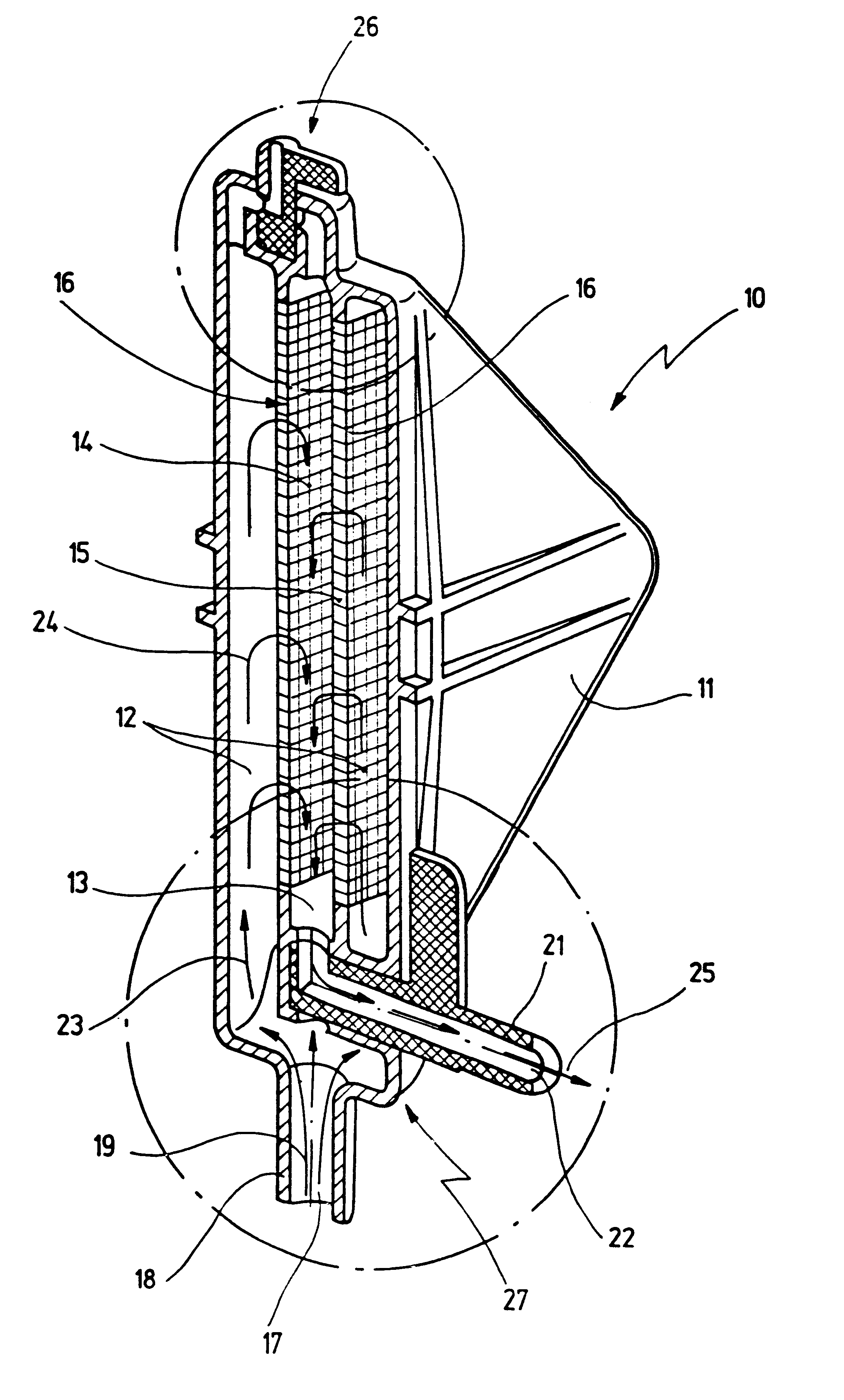
FIG. 1 shows, in a perspective longitudinal section, an apparatus 10 for filtering and degassing body fluid, which in the selected embodiment is a blood filter. Apparatus 10 is configured as a dead-end filter, so that (in contrast to crossflow filters) blood loss during use is avoided.

Apparatus 10 comprises a prismatic housing 11 in which a first filter chamber 12 and a second filter chamber 13 are arranged.

Second filter chamber 13 is delimited by two side walls 14, 15, respectively fitted with a filter medium 16 that separates first filter chamber 12 from second filter chamber 13.

At its point that is lowest in the operating position shown in FIG. 1, apparatus 10 has an inlet 17 at an inflow connector 18, through which a body fluid flow indicated at 19 passes into first filter chamber 12. Located directly adjacent to inflow connector 19 is an outflow connector 21 with an outlet 22.

Body fluid flow 19 passing into apparatus 10 rises upward in first filter chamber 12, as indicated by a...


PUM

PropertyMeasurementUnit
Flow rateaaaaaaaaaa
Shapeaaaaaaaaaa

Abstract

An apparatus for filtering and degassing body fluid has two filter chambers, separated from one another by a filter medium. The first filter chamber is connected to an inflow connector, and the second filter chamber to an outflow connector. An aeration and venting device common to the two filter chambers which is connectable selectably and separately to the first or the second filter chamber.

Description

1. Field of the InventionThe present invention relates to an apparatus for filtering and degassing body fluids, in particular a blood filter, having at least two filter chambers, separated from one another by a filter medium, that are preferably arranged in a common housing, the first filter chamber being connected to an inflow connector for body fluid that is to be filtered, and the second filter chamber to an outflow connector for filtered body fluid.2. Related Prior ArtAn apparatus of this kind is known from DE 35 41 521 C2.The known apparatus is a blood filter whose inflow connector, in the operating position, is connected vertically from below to the first filter chamber. The inflow connector leads into a rising tube that passes through the cylindrical first filter chamber to approximately two-thirds of its height. The blood being filtered emerges at the top from the rising tube, which is configured as an overflow, and falls along the outside of the rising tube into a sump.As t...

Claims


Application Information

Patent Timeline
IPC IPC(8): A61M1/36A61M5/38A61M5/36A61M1/00
CPCA61M1/3627A61M5/38
Inventor SPRANGER, MARTIN
Owner JOSTRA AG
Why Eureka
Try Eureka