
Actuating apparatus for automated constituents of power trains in motor vehicles

a technology of actuating apparatus and power train, which is applied in the direction of sawing apparatus, galvano-magnetic hall-effect devices, driver input parameters, etc., can solve the problems of large number of parts, large space occupation of hydraulically operated actuators or actuators, cost and bulk of clutches and/or gearboxes,

Inactive Publication Date: 2001-12-11
LUK GETRIEBE SYST
View PDF13 Cites 37 Cited by
  • Summary
  • Abstract
  • Description
  • Claims
  • Application Information

AI Technical Summary

Benefits of technology

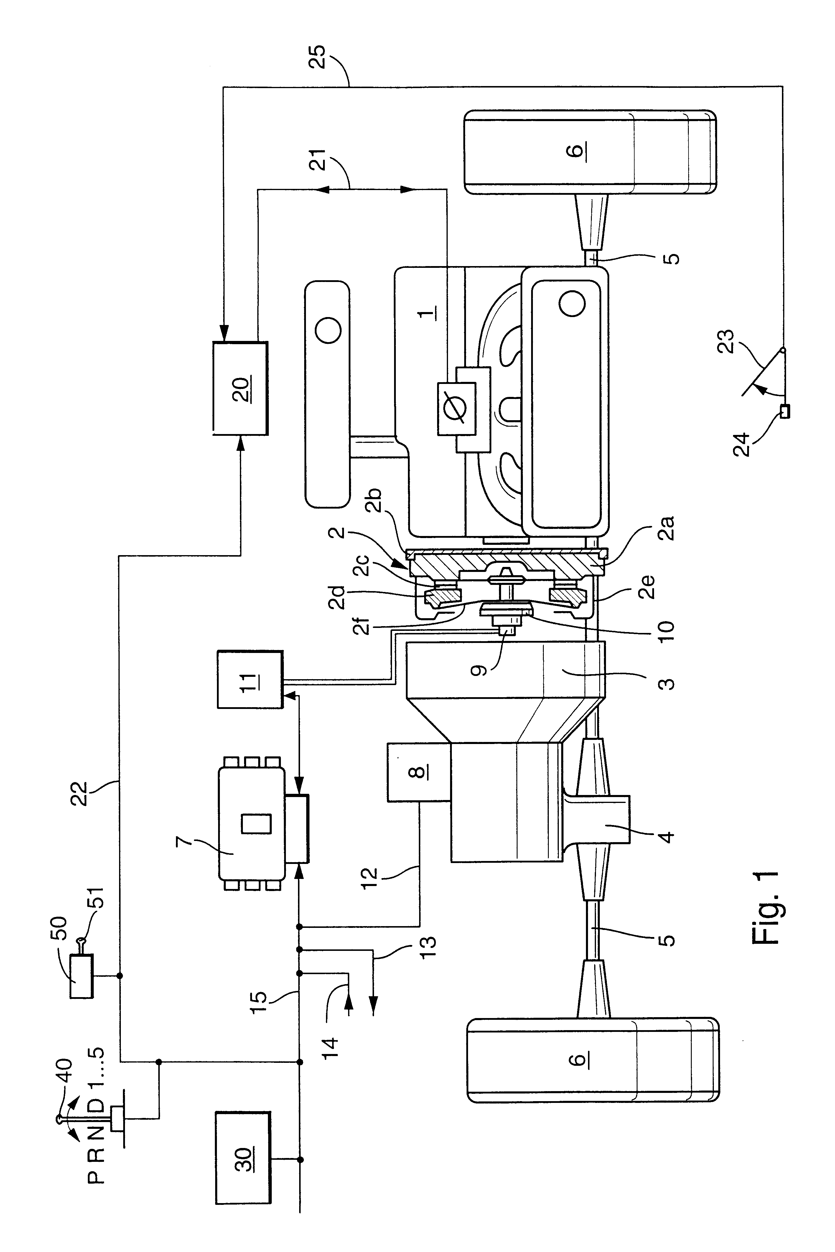
An object of the invention is to provide the power train of a motor vehicle with novel and improved (such as compact, simple and inexpensive) actuating means for one or more automated parts of the power train.
A further object of the invention is to provide a power train which is designed to simplify the tasks of the operator of a motor vehicle and which contributes to the comfort and safety of the occupant(s) of the motor vehicle.
A further object of the invention is to provide a novel and improved (particularly compact, simple, reliable and inexpensive) power train which can be utilized with advantage in existing makes of motor vehicles.
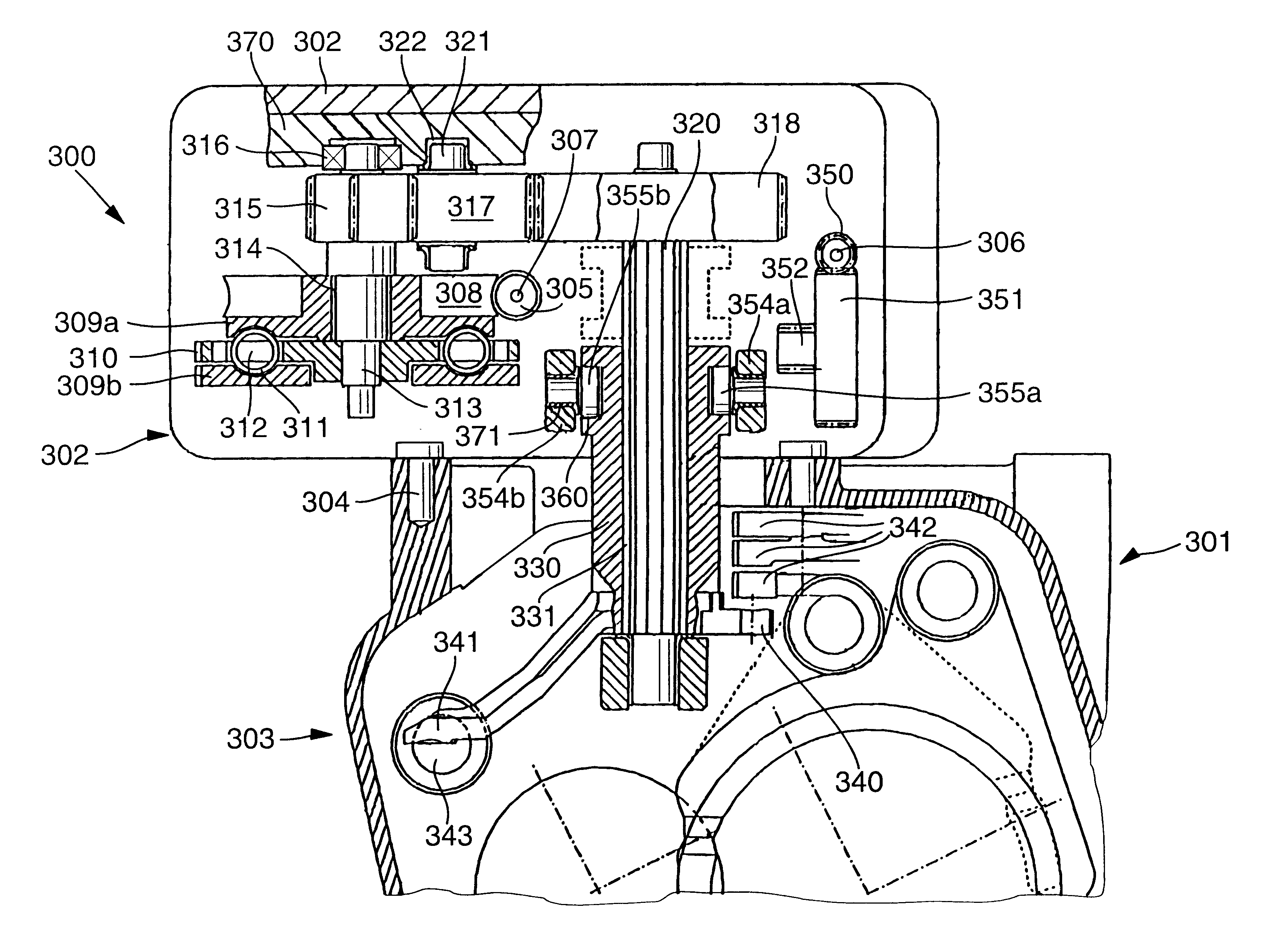
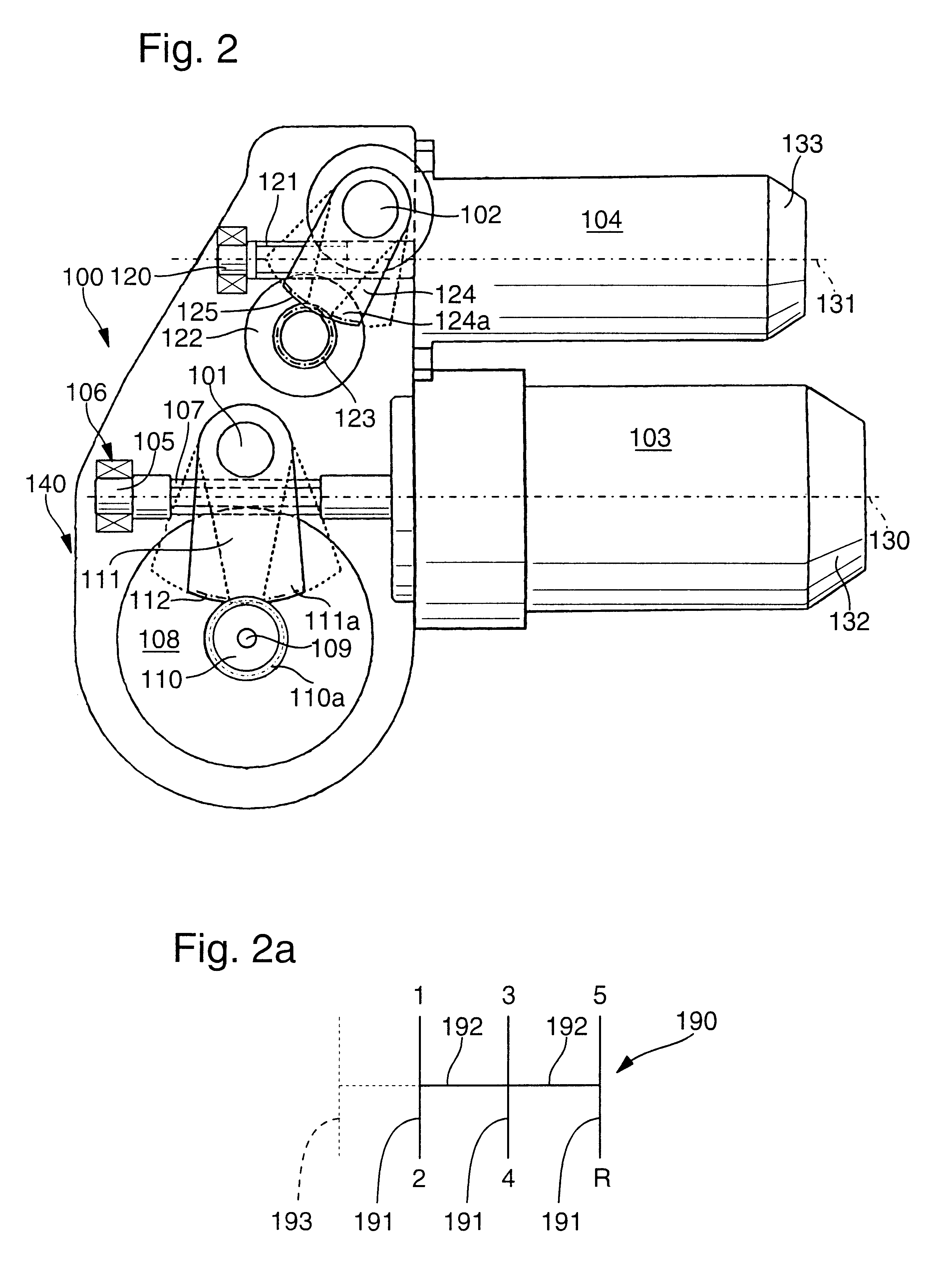
The first and second driving units can respectively include first and second members (such as rotary output shafts of electric motors) which are rotatable about first and second axes, and each of the transmissions can include a worm gearing having a worm wheel. The two worm wheels and the axes of the aforementioned first and second members can be located in a common plane. In many power trains, such positioning of the just enumerated parts can entail substantal savings in space or a most economical utilization of space which is available for the actuating means of the improved power train.

Problems solved by technology

A drawback of such clutch or gearbox actuating means is that the hydraulically operated actuator or actuators occupy much space and comprise a large number of parts.
This contributes to the cost and bulk of the clutch and / or gearbox, to the cost and bulk of the actuating means for the clutch and / or gearbox, and to the cost and bulk of the entire power train.
Another drawback of heretofore known power trains which comprise automated torque transmitting systems and / or automated gearboxes is that the sensors which they employ to monitor the speed, acceleration, distances covered and / or other parameters which are to be considered for automatic shifting of a gearbox and / or for automatic selection of torque to be transmitted by an automated clutch are too bulky and / or unreliable and / or insufficiently sensitive for utilization in such power trains.

Method used


Image

  • Actuating apparatus for automated constituents of power trains in motor vehicles
  • Actuating apparatus for automated constituents of power trains in motor vehicles
  • Actuating apparatus for automated constituents of power trains in motor vehicles

Examples


first embodiment

a monitoring arrangement which operates with a single sensor 605 is shown in FIGS. 15a and 15b. The monitored means includes two coaxial disc-shaped elements 601, 602 which can respectively replace the composite element 270a-270b and the one-piece element 271 of FIG. 5c. Each of the elements 601, 602 includes a magnetized or magnetizable radially outer (marginal or peripheral) portion or zone. The element 601 is assumed to transmit torque to the element 602 against the opposition of at least one energy storing element (not shown in FIGS. 15a and 15b). The energy storing element (e.g., a set of coil springs to be described with reference to FIGS. 17c-17d and 18a-18a) opposes rotation of the element 602 with the element 601, i.e., the setting of the element 602 in rotary motion in response to rotation of the element 601 involves at least some stressing of the energy storing element.

The marginal zones of the elements 601, 602 are magnetized in such a way that they exhibit annuli of alt...


PUM


Abstract

A power train for us in a motor vehicle has a prime mover (such as a combustion engine), an automated gearbox which transmits torque to the wheels of the vehicle, a friction clutch between the prime mover and the gearbox, a computerized control unit which receives signals from several sensors, and one or more actuators which operate the clutch and / or the gearbox in response to signals from the control unit. The actuator for selecting the gear ratio of the gearbox and for shifting the gearbox into and from selected gears employs two transmissions each of which has a worm gearing receiving torque from a discrete electric motor of the actuator and a spur gearing which transmits motion from the respective worm gearing to a mobile component of the gearbox. The connection between the worm and spur gearings in at least one of the transmissions can comprise a damper cooperating with one or more sensors serving to transmit signals to the control unit.

Description

The invention relates to motor vehicles in general, and more particularly to improvements in power trains for use in motor vehicles. Still more particularly, the invention relates to improvements in arrangements for actuating or operating automated torque transmitting systems (such as friction clutches or hydrokinetic torque converters with lockup or bypass clutches) and / or automated transmissions (hereinafter called gearboxes) in the power trains of motor vehicles.It is known to operate or actuate an automated gearbox or an automated clutch by a control unit which receives signals from one or more sensors, electronic circuits and / or other monitoring means and transmits signals to one or more actuators which directly actuate or operate a gearbox to select a particular gear ratio and / or to shift into a selected gear ratio; the same actuator or additional actuator(s) can be utilized as a means for automatically selecting the. torque to be transmitted by an automated clutch or another ...

Claims


Application Information

Patent Timeline
Patent Type & Authority Patents(United States)
IPC IPC(8): F16H59/70F16H61/28F16H61/32
CPCF16H59/70F16H61/32B60K41/22Y10T74/2003F16H2061/2892Y10T74/18792Y10T74/19251F16H2063/3089B60W10/02B60W10/11B60W30/18B60W2510/1015B60W2540/16B60W2710/1005B27B5/187B27B5/32B27B29/02
Inventor ROGG, ANDREASDEIMEL, ANDREAS
Owner LUK GETRIEBE SYST
Learn More