
Microelectromechanical systems (MEMS) -type devices having latch release and output mechanisms

Inactive Publication Date: 2001-11-27
ARMY GOVERNMENT OF THE UNITED STATES OF AMERICA AS REPRENSENTED BY THE SEC OF THE
View PDF3 Cites 170 Cited by
  • Summary
  • Abstract
  • Description
  • Claims
  • Application Information

AI Technical Summary

Benefits of technology

It is another object of the present invention to provide novel MEMS-type latch / release anchor mechanisms and latching output relay mechanisms, which incur lower production cost compared to current macro-sized devices having similar capabilities.
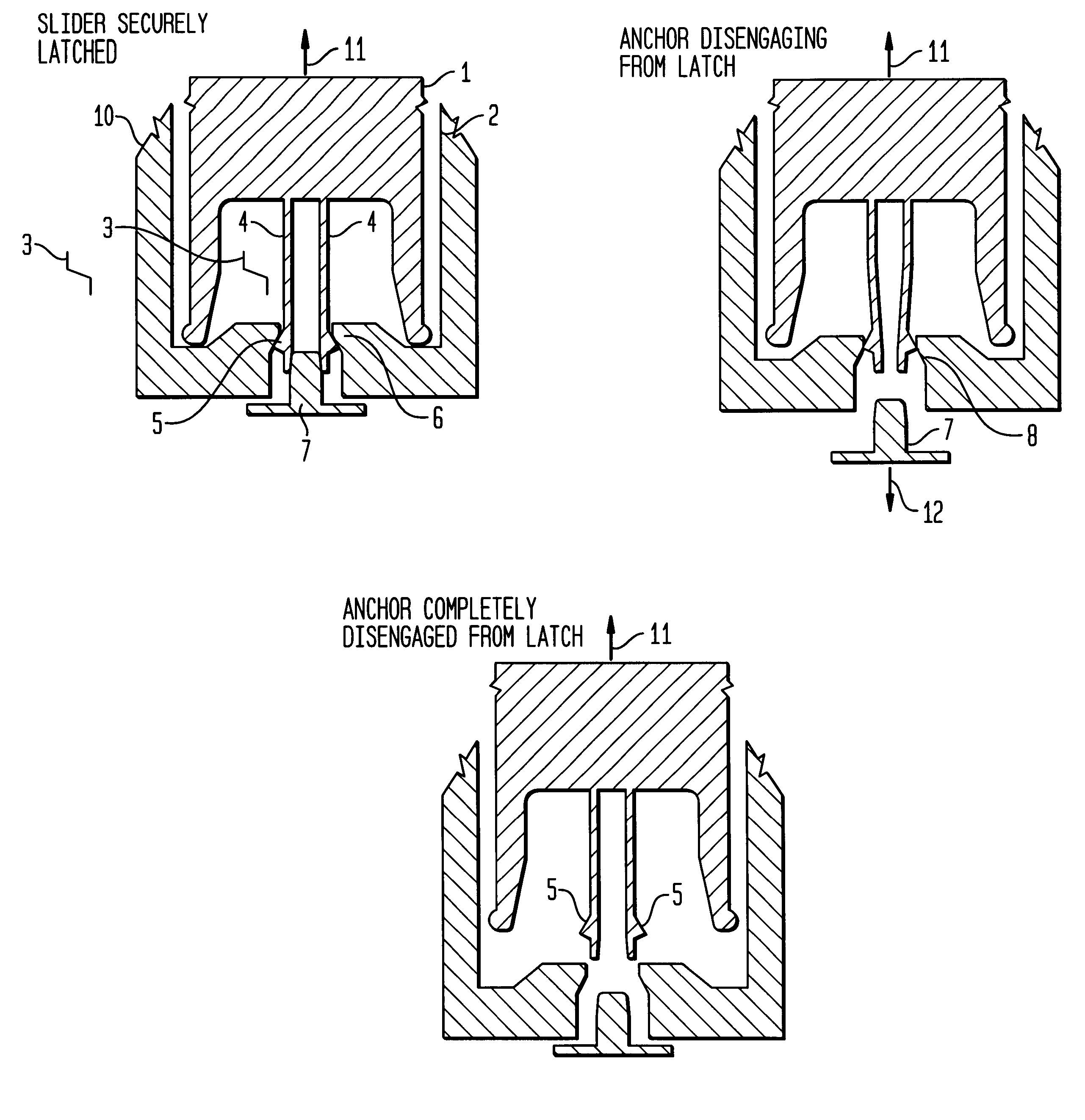
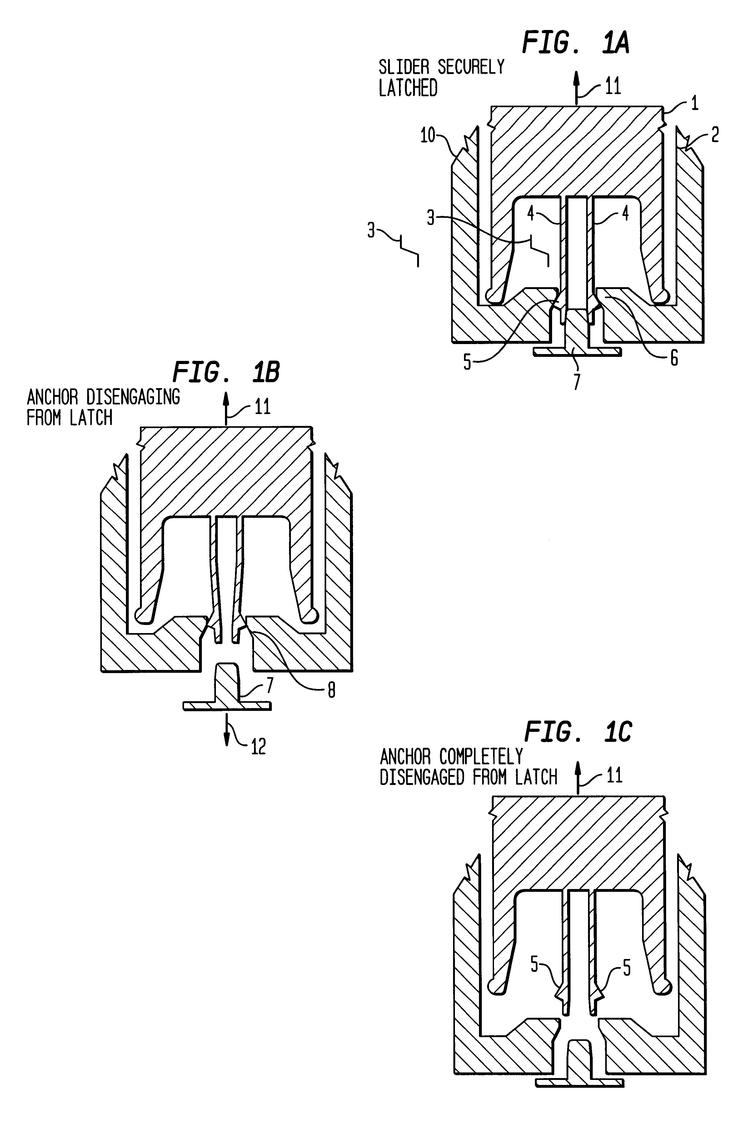
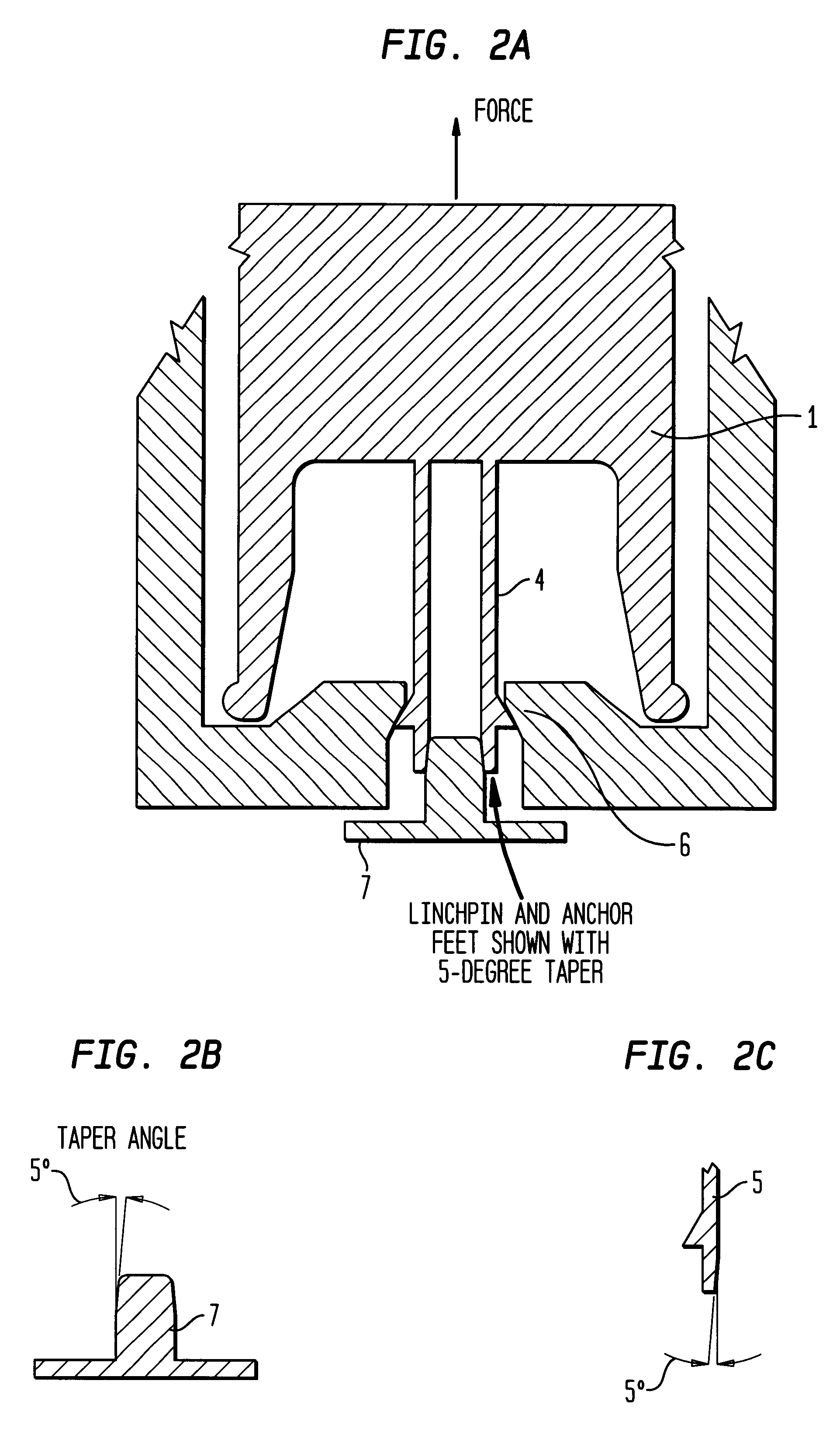
A first embodiment of the invention comprises a miniature release and latch anchor assembly that can be fabricated in combination with other moving and fixed elements on a single substrate. Such a release and latch anchor assembly has many applications in MEMS-type devices, particularly those devices whose moving elements react in response to a predetermined inertial loading impetus externally imposed thereupon. Applications of the invention include industrial, commercial, military, or space-type use. In particular, this embodiment provides ways of imposing or enforcing sequential operations of moving parts in a MEMS-type device, a necessity for safe and proper arming of projected munitions. Generally, such munitions must experience a sequence of input conditions prior to arming the fuze. More particularly, this embodiment's release and latch anchor assembly comprises a relatively massive slider member having anchor foot members attached by leg members. The slider member is secured by constriction members attached to a substrate base and a latching linchpin member interposed between the leg members. These components are formed on a single die. When the MEMS-type device experiences an initiating event to enable the release functioning of this embodiment, the anchor linchpin member disengages and allows the slider member to move within a track that is also attached to the substrate base. The anchor foot members have a one-way catch that prevents relatching of the slider member once the anchor legs slide out from and egress from these constriction members that are attached to the base. Then, when subsequent inertial loading of the MEMS-type device occurs, the slider member can effectuate proper sequential functioning of the device.

Problems solved by technology

However, fabrication of such devices is costly since such devices are constructed from extremely precision components, often requiring time-consuming component sorting, thus limiting their use.
Finally, such devices also include arrangements wherein mechanical sequential interlocks control the motion of the slider / rotor such that an out-of-sequence actuation of the interlocks leads to a fail-safe condition.
Overall, prior art arrangements are such that mechanical fuze S&A devices comprise complicated, three-dimensional assemblies of piece-parts working together inside of a frame, collar or support housing.
Furthermore, there is need for development of fuze S&A device designs that allow fuze developers and manufacturers to make changes to design thereof involving non-complex exposure-mask and process-parameter changes to the MEMS micromachining process, compared to expensive factory retooling currently used to achieve the same goal when using conventional mechanical components.
MEMS-type devices are potentially lower in cost to produce, due to the use of microelectronic fabrication techniques and when properly designed, MEMS-type actuators can produce useful forces and displacement, while consuming reasonable amounts of power.

Method used


Image

  • Microelectromechanical systems (MEMS) -type devices having latch release and output mechanisms
  • Microelectromechanical systems (MEMS) -type devices having latch release and output mechanisms
  • Microelectromechanical systems (MEMS) -type devices having latch release and output mechanisms

Examples


first embodiment

Operation of the First Embodiment

While Latched: The anchored or latched slider member shown in FIG. 1a, is strongly secured. No force in lateral, up, or down directions can pull the anchor feet free of the constriction so long as the linchpin remains in place between the feet, the tensile strength of the anchor legs is not exceeded, and a cover plate holds the moving parts in plane, see FIG. 15. Thus the device is capable of "holding off" large forces or loads encountered in civilian or military applications. These loads especially include those associated with the military logistic environment, such as transportation vibration, and handling / mishandling drop impacts, as well as those of munitions loading in the breech of a gun. The invention can "hold off" these forces or loads while still being responsive and functional when the proper launch environments are encountered.

Latch Releasing: Latch release shown in FIG. 1b is effected by moving the linchpin downward from between the anc...

second embodiment

the invention provides an additional functioning to the first embodiment discussed above wherein the slider mass can go from a free / unlatched position into a latched / anchored position or a latched / enabled position. The sequences of operational events of this embodiment are similar to the operations of the first embodiment as discussed above and the slider member can start out in its free position as shown in FIG. 4a and move downward to become anchored and locked, see FIG. 4b and 4c. Next, the slider member can start out in its free position as shown in FIG. 4a and move downward to become anchored but not locked. "Latched" refers to the anchor feet are fully inserted into the latch / constriction, "not locked" means that the linchpin is not inserted between the anchor feet. In this latched / non-locked condition, the slider mass is enabled to respond to a force input to go unanchored again. Subsequently, the linchpin can be caused to re-insert itself between the anchor feet. Because the...

third embodiment

of the Invention

Referring to the FIGS. 7-13, various mechanical output pin assemblies (discussed in FIG. 14) that are preferably used in combination with a MEMS-type S&A device are shown. These output pin assemblies in association with an integrated or coupled MEMS-type or miniature non-MEMS-type device provide mechanical closing or opening of an output function as shown in FIGS. 7 and 8 or mechanical displacement of an optical fiber shown in FIG. 9.

In FIG. 7a, the flexible electrical contact arm 80 is deflected upwards by the action of the mechanical output pin 25 when it is extended by the action of the actuation slider 82 to where it pushes against an electrical contact 81 and thus closes an electrical circuit. In FIG. 7b, the circuit is shown closed by the action of the mechanical output pin 25 pressing the contacts together.

In FIG. 8a, a normally closed (NC) switch configuration is shown in which the contact arm 80 and contact 81 are already in contact and the action of the mec...


PUM


Abstract

A first embodiment of the invention comprises a miniature release and latch anchor assembly that can be fabricated in combination with other moving and fixed elements on a single substrate (3). Such a release and latch anchor assembly has many applications in MEMS-type devices, particularly devices whose moving elements react in response to predetermined inertial loading inputs externally imposed thereupon. This embodiment provides ways of imposing or enforcing sequential operations of moving parts in a MEMS-type device, a necessary operational requirement for safety and proper arming of projected munitions. A second embodiment of the invention is a variation of the first embodiment wherein a reinsertable-re-releasable latch anchor assembly mechanism has insertable anchor feet members (5) in cooperation with the linchpin member (7) whereby re-latching of the anchor assembly can occur. A third embodiment of the invention comprises various designs of mechanical output pin (25) in various assemblies for relay functioning. These output pin assemblies are part of an integrated or coupled MEMS-type device that mechanically closes or opens an output actuated device such as a valve, electrical contacts or optical transmitting device.

Description

U.S. GOVERNMENT INTERESTThe invention described herein may be manufactured, used, and licensed by or for the U.S. Government for U.S. Government purposes.The present invention relates generally to microelectromechanical systems (MEMS)-type devices and, more particularly, to MEMS-type devices having latch, release and output mechanisms for use in fuze safety and arming devices.DESCRIPTION OF THE PRIOR ARTExplosive projectiles, such as mortar shells, artillery shells and other similar projectiles, normally have a S&A device, which operates to permit detonation of the explosive only after the projectile has been fired or launched. Thus, mechanical arming delay mechanisms for such projectiles or explosives are well known in the art.For example, three-dimensional rotary or linear zigzag delay (that is, inertial delay) devices on the scale of millimeters or centimeters, fashioned by precision machining, casting, sintering or other such "macro" means, have previously been used to provide a...

Claims


Application Information

Patent Timeline
IPC IPC(8): F42C15/00F42C15/24H01H1/00H01H35/14
CPCF42C15/24H01H1/0036H01H35/14H01H2001/0047
Inventor ROBINSON, CHARLES H.
Owner ARMY GOVERNMENT OF THE UNITED STATES OF AMERICA AS REPRENSENTED BY THE SEC OF THE
Learn More