
Vehicle body side structure

a side structure and vehicle technology, applied in the field of vehicle body structure, can solve the problems of deformation of the center pillar, the strength of the door, and the inability to compress one or both

Inactive Publication Date: 2001-11-06
NISSAN MOTOR CO LTD
View PDF8 Cites 40 Cited by
  • Summary
  • Abstract
  • Description
  • Claims
  • Application Information

AI Technical Summary

Problems solved by technology

In actual side collision cases, however, the front portion of a colliding vehicle hits not only the center pillar but also one or both doors of the vehicle and compresses one or both of the doors.
The door, on the other hand, generally has a weaker strength than center pillar against an external surface force generated during a side collision, since the door is made of a paneling material with many openings.
If the door is moved more towards the interior of the vehicle relative to the center pillar or structural member, as mentioned above, the door pulls the center pillar via an engaging mechanism, which results in deformation of the center pillar.
Accordingly, although the above-mentioned deformation of the center pillar will be avoided by using conventional technique, there is a disadvantage in the increase of weight.
Accordingly, there is a disadvantage in prior art in that the width of a vehicle may be significantly increased.
Therefore, the load applied to the door is transmitted to the center pillar and the above-mentioned problem is not solved by this technique.

Method used


Image

  • Vehicle body side structure
  • Vehicle body side structure
  • Vehicle body side structure

Examples


second embodiment

In this modified embodiment, the collision sensor 16 outputs a collision signal to the controller 18 when the vehicle 17 makes an extraordinary approach from the side direction, and the door release mechanism 13 releases the engagement of the door 3 before the vehicle 17 collides. Accordingly, in this second embodiment, measures can be taken before the collision and can be fully prepared for the collision. However, it is necessary, if an actual collision has not occurred for a few seconds after the actuation of the door release mechanism 13, that the controller 18 output an engagement signal to the door release mechanism 13 so that the striker 11 returns to a normal engagement state and causes no hindrance for normal operation of the vehicle.

FIGS. 20-22 are diagrams for showing the air bag 21 of the second embodiment of the present invention. FIG. 20 is a perspective view of the door 3 with the air bag 21 packed in the door 3 as viewed from the cabin. FIG. 21 is a perspective view o...

first embodiment

Also, when the controller 18 receives a collision signal from the collision sensor 16, it immediately outputs an inflate air bag signal to the inflator I for the air bag 21 as well as a door release signal to the door release mechanism 13 to release the door engagement as in the above-mentioned

Next, the operation of the above-mentioned configuration will be explained with reference to the flow chart in FIG. 24. As seen in FIG. 24, a flowchart is shown that represents an algorithm for a program for the controller 18 when used in connection with the third embodiment of the present invention. In this embodiment, the algorithm of the controller 18 outputs a door release signal and an inflate airbag signal in response to a signal from collision sensor 16. In step S11, the controller 18 determines if a collision or crash is expected. If no collision signal is received by the controller 18 from the collision sensor 16, the controller proceeds to step S12, where the controller 18 outputs a ...

third embodiment

Referring now to FIGS. 25-30, a third embodiment is illustrated according to the present invention. FIG. 26 is an exploded perspective view of the door 3 with a air of frame members 22 each having a fragile portion 22a. FIG. 27 is a perspective view of the door 3 after the fragile portions 22a of the frame members 22 are bent as viewed from the interior of the vehicle. FIG. 28 is a partly cut-out plan view of the entire vehicle 20 as viewed from the top of the vehicle. FIG. 29 is a diagrammatic view showing the occupant 19 and the door 3 prior to a collision as viewed from the top of the vehicle 20. FIG. 30 is a diagrammatic view showing the door 3 and the occupant 19 after the side collision as viewed from the top of the vehicle 20.

In this third embodiment, explanation of structures that are the same as in the first embodiment are omitted for simplicity and only structures different from the first embodiment will be explained. Also, in the figures, the same numerals are used for el...


PUM


Abstract

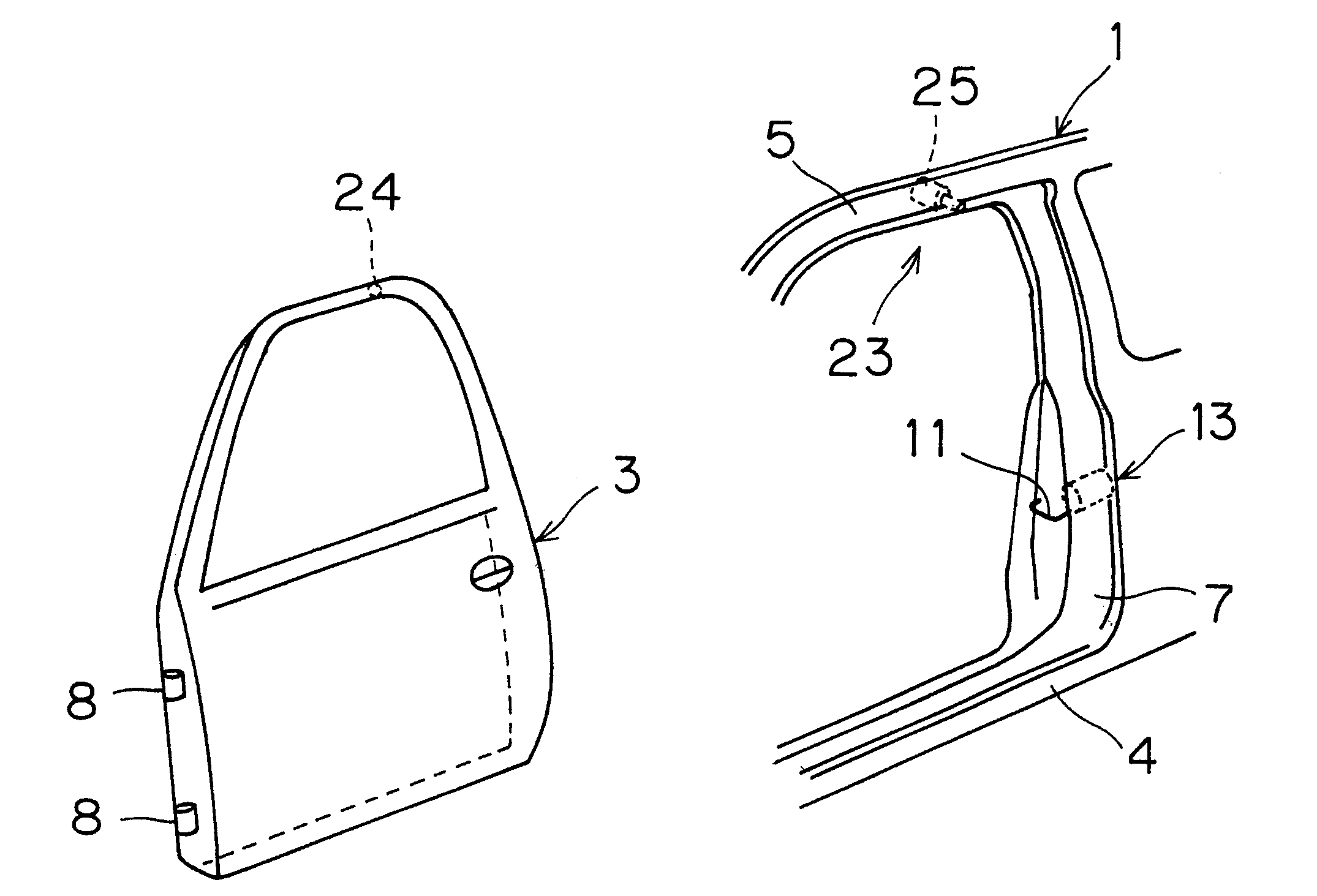
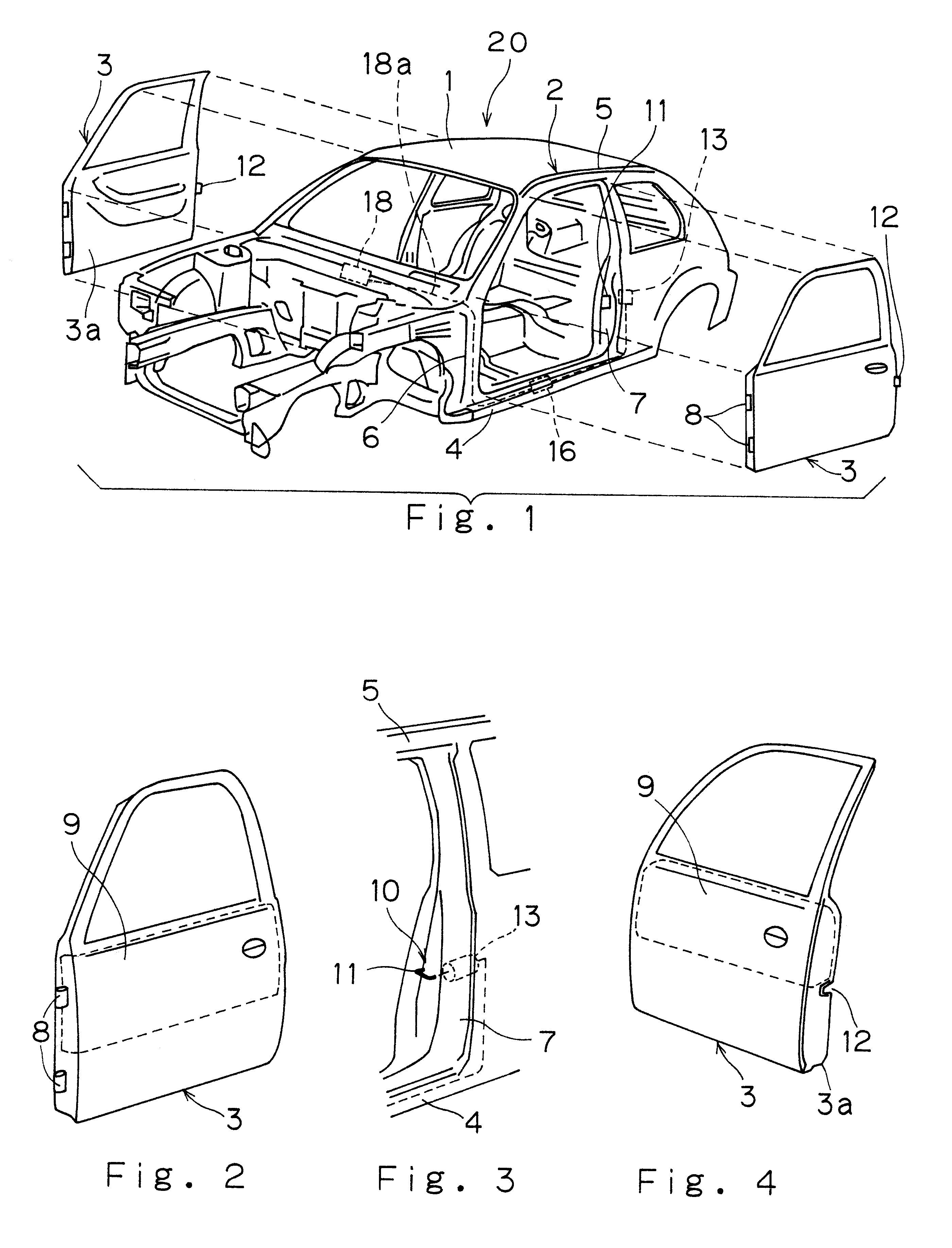
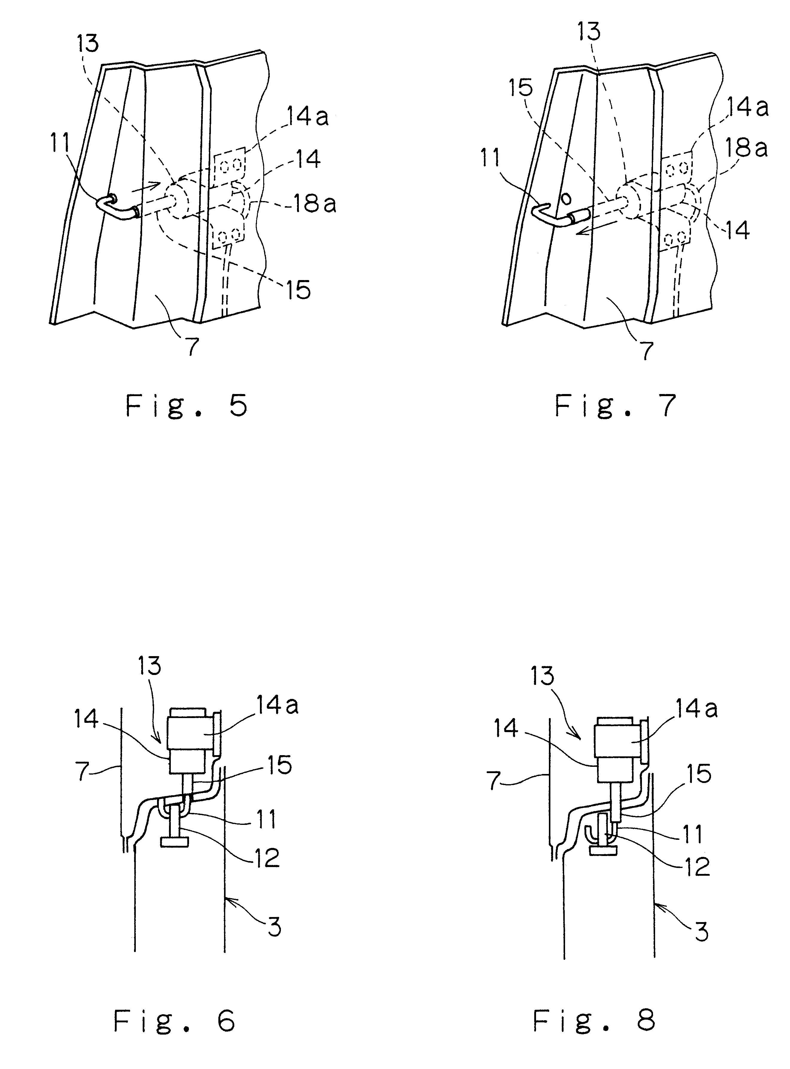
A vehicle body side structure is provided to prevent deformation of a structural member due to deformation of a door during a side collision. The vehicle body structure reduces the possibility that the structural member contacts an occupant and obtains an excellent impact absorption effect when the door contacts the occupant. The vehicle body structure has a body side portion with the structural member, and a door coupled to the body side portion to open and close relative to the structural member. An energy absorption member is coupled to the door. A door engagement mechanism is coupled between the door and the side structural member. The door engagement mechanism is arranged to hold the door and the structural member together. A collision sensor generates a collision signal when a side collision is detected by the collision sensor. A door release mechanism is connected to the door engagement mechanism to release the door from the structural member in response to the collision signal. The energy absorption member can be a block of compressible material located in the door, or an air bag, or a frame member with a fragile portion.

Description

1. Field of the InventionThis invention relates to a vehicle body structure. More specifically, the present invention relates to a vehicle body structure for reducing an impact of occupants in a vehicle during a side collision.2. Background InformationA vehicle body structure typically has one or more swingably mounted doors that latch to a center pillar. The upper and the lower ends of the center pillar are welded to a side roof rail and a side sill, respectively. The cross section of the center pillar is formed with a closed cross section over its entire length between the side roof rail and the side sill. When another vehicle collides with the side of a vehicle having this type of side structure, the center pillar and the front and rear doors of the vehicle are compressed by the front portion of the colliding vehicle. More specifically, the center pillar or structural member tends to bend at the center towards the occupant. Since the height of the center portion of the center pil...

Claims


Application Information

Patent Timeline
Patent Type & Authority Patents(United States)
IPC IPC(8): B62D25/04B62D25/00B62D25/02B60J5/00B60R21/0136B60R21/02B60R21/16B60R21/20B60R21/21E05B77/12E05B83/36
CPCB62D25/02B62D25/025B62D25/04Y10S292/65Y10T292/0825Y10T292/0826Y10T292/699
Inventor KITAGAWA, YUICHI
Owner NISSAN MOTOR CO LTD
Learn More