
Mobile cyclonic power wash system with water reclamation and rotary union

a technology of cyclonic power washing and rotary union, which is applied in the direction of cleaning with liquids, carpet cleaners, cleaning filter means, etc., can solve the problems of not being designed to be independent, the system is not designed to operate independently, and the operation of the prior art system is limited

Inactive Publication Date: 2001-10-16
NILFISK ADVANCE TECH
View PDF17 Cites 56 Cited by
  • Summary
  • Abstract
  • Description
  • Claims
  • Application Information

AI Technical Summary

Benefits of technology

A still further feature of this aspect of the invention is the construction of the filtration tank which includes an inlet at the top, a removable slanting trough below the inlet with a screened outlet at the bottom of the trough for filtering large matter from the water, a plurality of cascading chambers for allowing the water to successively fill a chamber and flow over into an adjacent chamber leaving behind smaller matter still present in the water continuously passing cleaner water to the next chamber, and a plurality of baffles for preventing matter and water from being directly vacuumed into the inlet of the vacuum pump system.
A further aspect of the invention is in the water cyclone sprayer of the power wash system, which sprays high pressure, high temperature water at a high rotating speed. The improvement in this sprayer is in the rotary union seal, which is formed between two silicon carbide surfaces, one stationary and the other rotatable at high rpm with the water passing through a central bore through the sealing members which prevents leakage through the rotary union seal, and an o-ring which prevents leakage around the rotary union seal.
A further feature of this aspect of the invention is the method of effecting the seals in the rotary union which includes non-rotatably, slidingly mounting within the central bore of the housing a cylindrical support member which has affixed to one end thereof a first silicon carbide seal face. The support member has a central bore therethrough and the sliding mounting forms an interface between the central bore of the housing and the outer surface of the cylindrical support member. The method further includes slidingly sealing the interface by sandwiching an o-ring between the other end of the cylindrical support member and a downwardly biased washer with the o-ring slidingly engaging the housing central bore, retainingly, rotatably supporting within another central bore of the housing a spindle having a second silicon carbide seal face affixed to that end of the spindle adjacent the cylindrical support member and having a central bore therethrough to its discharge end; thereby, forming a rotary union by sealingly engaging the first and second silicon seal faces. In this method fluid, i.e. water, entering the inlet end of the housing passes through the central bores of the members, o-ring, spindle and rotary union and out the discharge end of the spindle without leaking around or through the seal at the rotary union.
A further feature of this aspect of the invention includes supporting the inner bore of the o-ring by a downwardly axially extended inner bore portion of the biased washer and an upwardly axially extended inner bore portion of the other end of the cylindrical support member. This construction prevents the o-ring from being blown into the central bore of the cylindrical support member by the high pressure water present at the interface.

Problems solved by technology

One of the problems with the prior art power wash systems is that none of them provided any means for recovering, filtering, and recycling the water sprayed by the power wash system.
The prior art systems were not designed to be independent, self-contained systems in which the water is continuously reclaimed, filtered, and recycled for further use by the power wash system.
Therefore, the operation of the prior art systems is limited by the amount of water that can be stored or transported by the system (i.e. by the capacity of the water storage means), and the operator of the system was inconvenienced in having to replenish additional water from an outside source when the stored water was depleted.
In effect, these prior art systems required the use of large amounts of water, and these systems wasted the stored water since they did not have the capability of reclaiming and re-using it.
Moreover, environmental objections are increasingly being raised to harmful wastes being dumped into local drainage systems.
However, due to the high pressure and high temperature and high rpm environment in a cyclone power wash sprayer of the present invention, the prior art o-rings themselves cannot function as the primary sealing means between the stationary and rotating members of the sprayer.
Moreover, when positioned directly in the high pressure, high temperature water flow path as a bypass seal, the prior art fails to disclose the additional means required to prevent the o-ring itself from being carried away with the water flowing past it.
The problem with this system is that it uses a hard material, such as silicon carbide, for the rotating seal surface, while using a softer material, such as boron nitride, for the stationary seal surface.
Thus, the softer seal surface rapidly wears out against the harder seal surface.
The problem with the prior art rotary unions described above is that the parts of the rotary union wore out very fast because the device was operated under high pressure, high temperature and at high rpm.
The rapid wearing out of these parts caused the seal of the rotary union to leak with the result that the water cyclone sprayer could not function properly or effectively.

Method used


Image

  • Mobile cyclonic power wash system with water reclamation and rotary union
  • Mobile cyclonic power wash system with water reclamation and rotary union
  • Mobile cyclonic power wash system with water reclamation and rotary union

Examples


Embodiment Construction

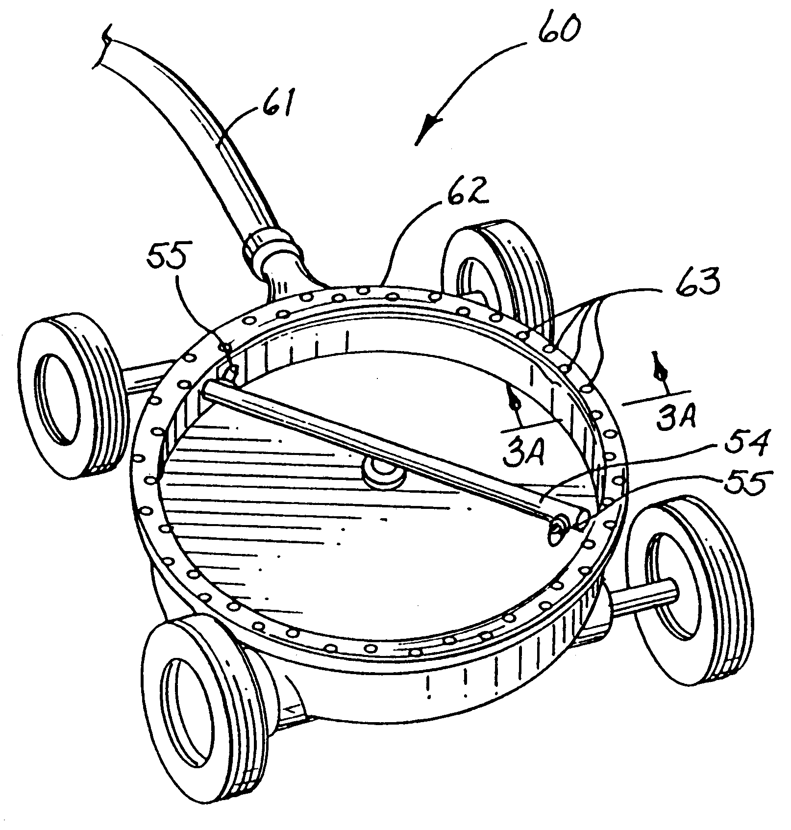
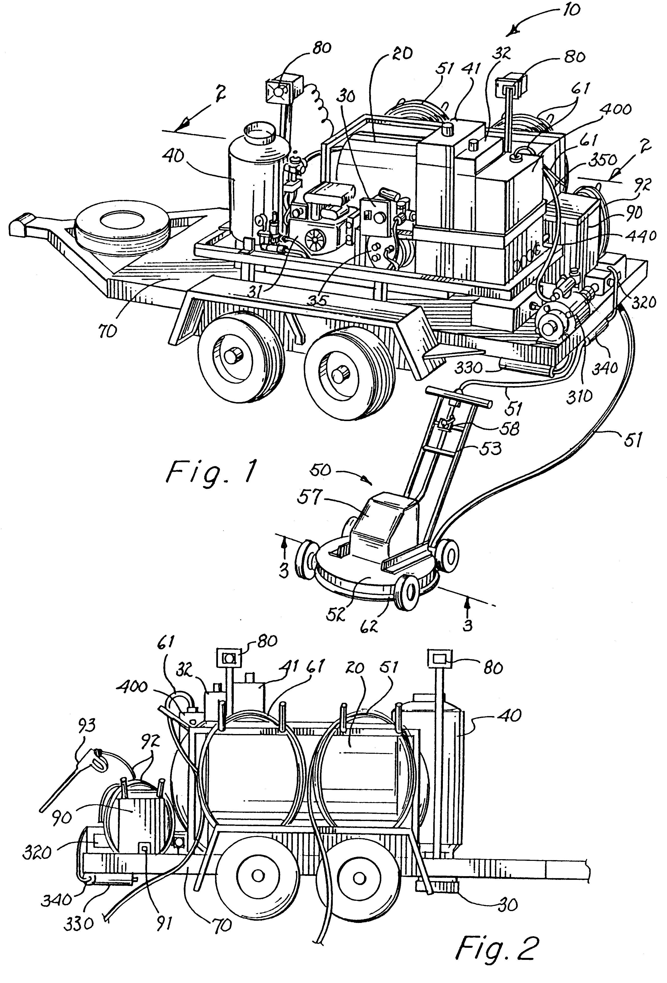
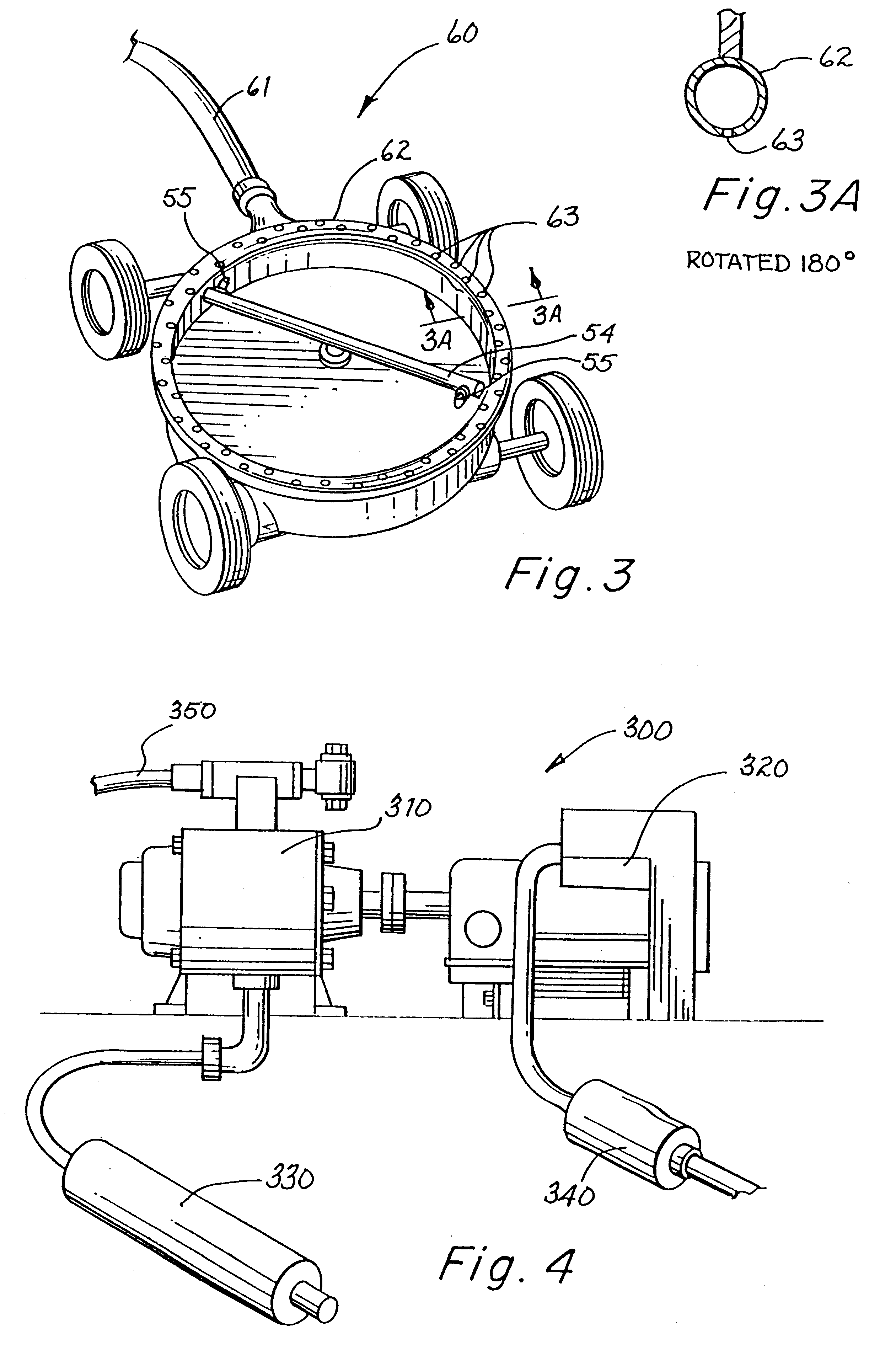
FIGS. 1 and 2 respectively show front and rear views of a mobile cyclonic power wash system 10 which includes the novel water reclamation and filter recycling system 60 (shown generally in FIG. 3 but also including elements shown in FIGS. 3A, 4 and 5) for reclaiming and filtering water that is sprayed by the system and recycling the filtered water into a storage means 20 so that the water is re-used for cleaning. FIGS. 7, 7A and 8 respectively show elevation views of a first subassembly of components 110 and second subassembly of components 150 for an improved rotary union 100 (shown generally in FIGS. 7 and 8) used in the cyclonic power sprayer 50 in the power wash system 10. These features of the power wash system 10 are now described in more detail.

The Power Wash System

As seen in FIGS. 1 and 2, the mobile cyclonic power wash system 10 includes a water storage means 20 for holding the water to be used for cleaning by the system 10, a water pumping system 30 for pumping and pressur...


PUM

PropertyMeasurementUnit
Pressureaaaaaaaaaa
Angular velocityaaaaaaaaaa
Temperatureaaaaaaaaaa

Abstract

A cyclonic power wash system uses high pressure, high temperature water for selectively cleaning large, flat, concrete or asphalt surfaces. The sprayed water is reclaimed by vacuuming it through holes in the bottom of a reclamation ring attached to the underside of the mobile cyclone sprayer, filtering the vacuumed water and returning it to a storage tank for re-use by the system. The filtration tank initially filters out large matter in an inlet trough and smaller matter in a plurality of cascading chambers. A rotary union in the sprayer prevents the water, passing from the inlet of the rotary union to the discharge thereof, from leaking through or around a seal formed by pressing together a pair of hard, durable sealing surfaces, for example, silicon carbide, one of which is non-rotatably slidingly received in an upper recess of the union's fixed housing and the other, affixed to a spindle rotatably received and retained in a lower recess of the housing. The sliding fit interface of the non-rotatable seal face in the upper recessed housing is sealed by an o-ring supported at its inner bore by extended portions adjacent the central bores of the members between which it is sandwiched. Upward and rotational forces are applied to the spindle in reaction to the water exiting from nozzles affixed to a spray bar attached to the spindle.

Description

1. Fields of the InventionThe present invention relates generally to a mobile cyclonic power wash system that uses sprayed water for cleaning flat surfaces such as concrete, asphalt, and other various hard surfaces, and more particularly, to a power wash system having a system which reclaims and filters the sprayed water and recycles the filtered water to the system for further use in cleaning. The present invention also relates to a mobile cyclone sprayer that has an improved rotary union, which passes high pressure, high temperature water to a spray bar which rotates at high speeds, and more particularly, to an improved leakproof rotary union seal formed between a non-rotatable silicon carbide seal surface and a rotatable silicon carbide seal surface which prevents the water from leaking through or around the seal. The power wash system with these new and improved features provides more effective and convenient cleaning of flat surfaces.2. Discussion of Background and Prior ArtApp...

Claims


Application Information

Patent Timeline
IPC IPC(8): A47L11/38A47L11/40A47L11/00B05B3/02B05B3/06B08B3/02E01H1/10E01H1/00B05B3/08
CPCA47L11/38A47L11/4016A47L11/4027A47L11/4044A47L11/4088A47L11/4094B05B3/06B08B3/024E01H1/103B08B2203/0229B05B3/001
Inventor ROHRBACHER, RICHARD DAVIDJACOBSON, JUDITH MAE
Owner NILFISK ADVANCE TECH
Learn More