
Video decoding method, video decoder and digital TV system using the video decoding method and video decoder

a video decoding applied in the field of video decoding methods, video decoding and digital tv systems using the video decoding method and video decoding technology, can solve the problems of unstable decoding and display, complex circuit, and unstable display in real systems

Inactive Publication Date: 2001-09-25
LG ELECTRONICS INC
View PDF11 Cites 61 Cited by
  • Summary
  • Abstract
  • Description
  • Claims
  • Application Information

AI Technical Summary

Benefits of technology

Further another object of the present invention is to provide a video decoding method and a video decoder which can reduce decoding time by decoding the header of the next picture continuously in advance when decoding a picture data based on a single synchronization signal.

Problems solved by technology

First, it decodes the compressed video bit stream using DTS,PTS generated on the basis of STC, and displays it. And DTS,PTS signal intervals are not uniform because STC is 27 MHz and unstable clock that varies by surrounding conditions such as noises at the time of transmission. Accordingly, decoding and display become unstable, and especially, display in real system becomes unstable.
Second, circuit becomes complex because digital TV that uses the above video decoder is variously formatted, and synchronization are also input variously according to their format.
Third, the above video decoder uses 3 frame memory to display sequentially when frame is missed or repeated by various reasons. But this brings about waste of memory when display part that have various capability of displaying such as display format transformation is connected to rear side in the case of multi-format video, due to redundancy with a prime memory of display part.

Method used


Image

  • Video decoding method, video decoder and digital TV system using the video decoding method and video decoder
  • Video decoding method, video decoder and digital TV system using the video decoding method and video decoder
  • Video decoding method, video decoder and digital TV system using the video decoding method and video decoder

Examples


Embodiment Construction

Reference will now be made in detail to the preferred 10 embodiments of the present invention, examples of which are illustrated in the accompanying drawings.

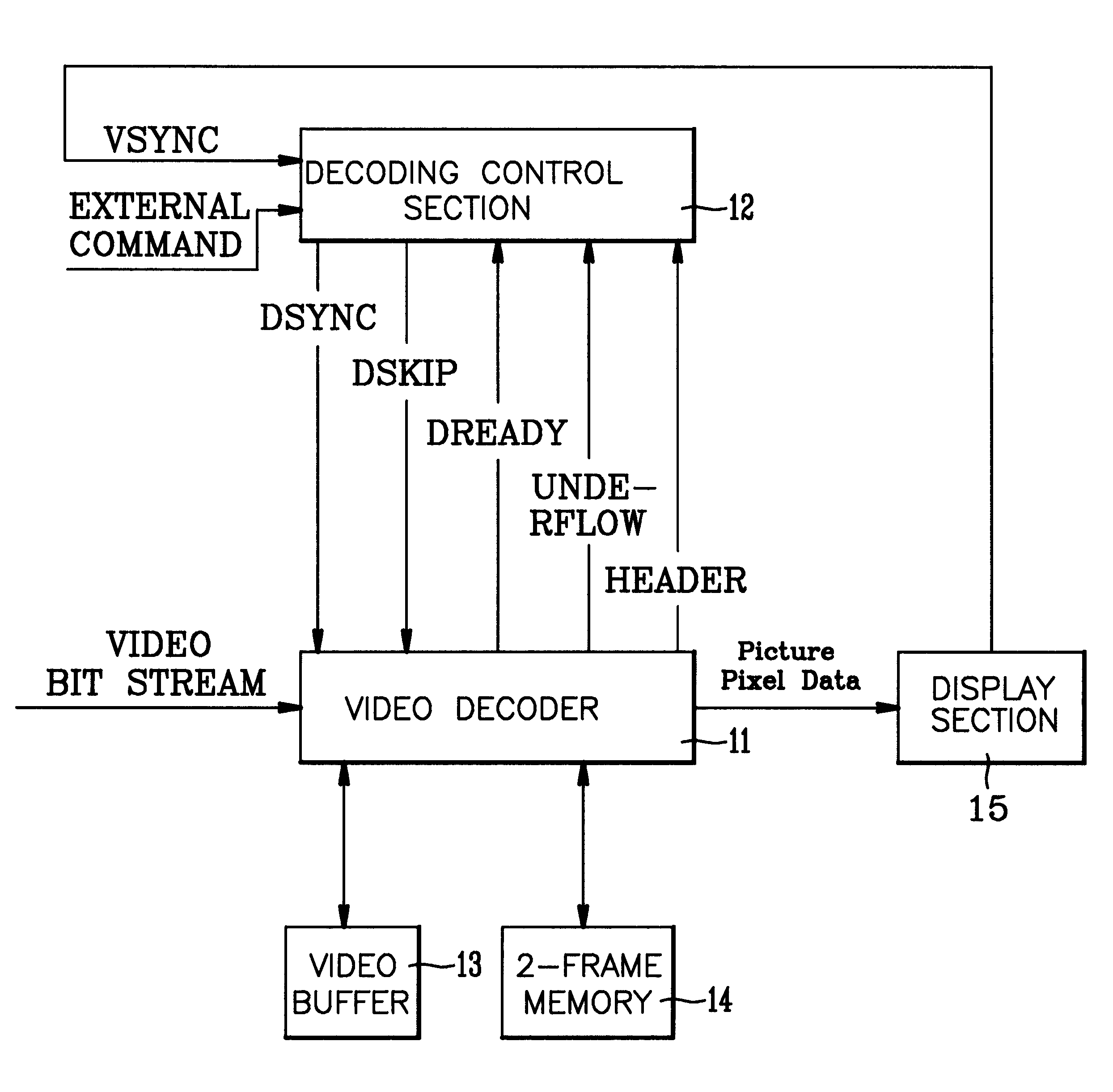
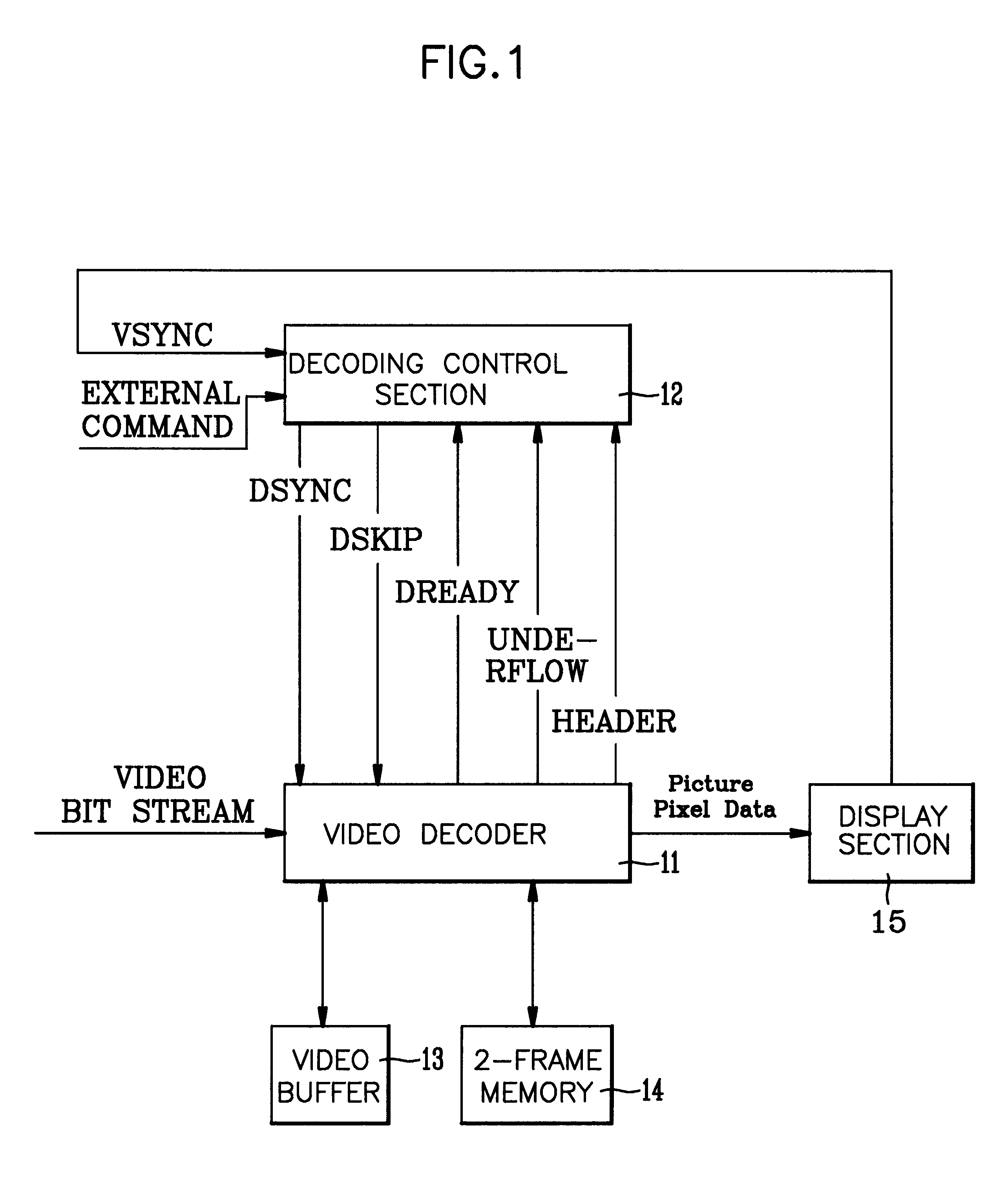
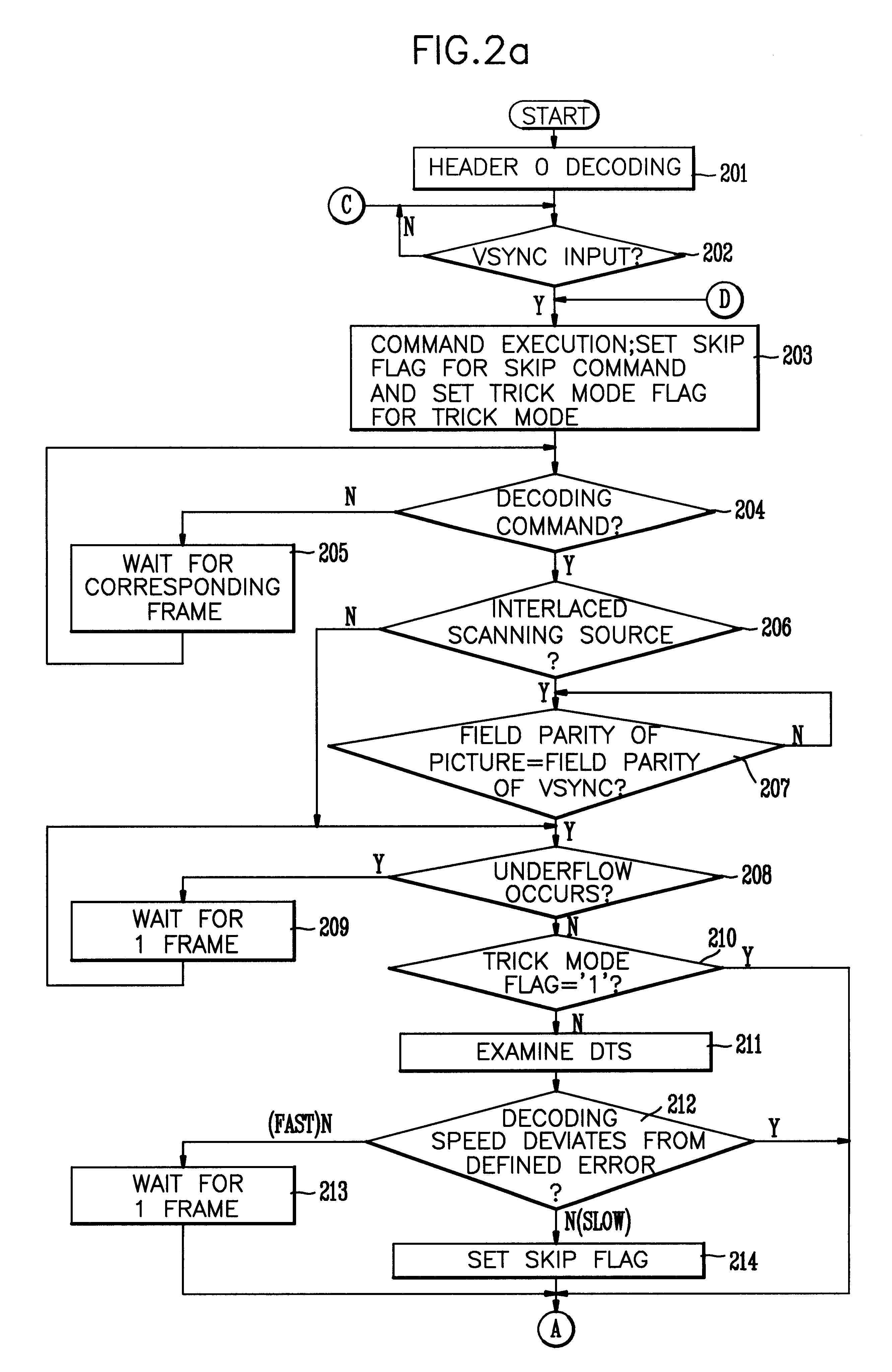
FIG. 1 is a block diagram showing the construction of a variable length video decoder according to the present invention. The video decoder comprises: a video decoder 11 for decoding a compressed video bit stream in the unit of picture based on a single vertical synchronization signal VSYNC to be output; a decoding control section 12 receptive to the single vertical synchronization signal VSYNC and an external command for controlling the decoding operation of video decoding section 11 by generating DSYNC and DSKIP signals to the video decoding section 11 under receipt of header information and underflow information from the video decoding section 11; a video buffer 13 for temporarily storing a video bit stream encoded at a variable rate and outputting it to the video decoding section 11 in order to decode the bit stream at a fi...


PUM


Abstract

A video decoding method and apparatus using the same decode and display a compressed video bit stream output through a video buffer for temporarily storing the video bit stream. The method includes the steps of (a) receiving a single sync signal and an external command to control decoding of the video bit stream; and (b) decoding the input video bit stream, or skipping it, or waiting without decoding under the control of step (a). A video decoder of the present invention includes a decoding control section receptive to a single synchronization signal and an external command to control decoding of the video bit stream, and a video decoder for decoding the video bit stream input through the video buffer, or skipping the video bit stream, or waiting for a defined frame period without decoding the video bit stream under the control of the decoding control section.

Description

1. Field of the InventionThe present invention relates to a video decoding method and a video decoder which is to decode a compressed video bit stream based on a single synchronization signal, and a digital TV system using the video decoding method and the video decoder.2. Discussion of Related ArtImage compression technology along with digitalization are essential factors in assisting multimedia. Recently data digitalization is making rapid progress, and image compression technology is highlighted.Moving pictures expert group (MPEG) is the standard of compression and encoding method of digital moving picture which is one of the most important factor in multimedia.Various technological fields use MPEG technology as compressing algorithm incluiding communication, broadcasting, game, etc. Digital TV is one of them.MPEG video compression algorithm is based on two basic technologies. It uses motion estimation and compensation in block units to reduce temporal redundancy, and uses discre...

Claims


Application Information

Patent Timeline
Patent Type & Authority Patents(United States)
IPC IPC(8): H04N7/24H04N7/50
CPCH04N21/6332H04N19/61H04N21/654H04N19/42
Inventor LYU, HWA YOUNG
Owner LG ELECTRONICS INC
Learn More