
Spray unit that atomizes liquid at the start of the spray operation

a technology of spray unit and liquid, which is applied in the direction of lighting and heating apparatus, combustion types, instruments, etc., can solve the problems of delayed start of liquid ejection and negative pressure generation

Inactive Publication Date: 2001-09-18
YOSHINO KOGYOSHO CO LTD
View PDF9 Cites 13 Cited by
  • Summary
  • Abstract
  • Description
  • Claims
  • Application Information

AI Technical Summary

Benefits of technology

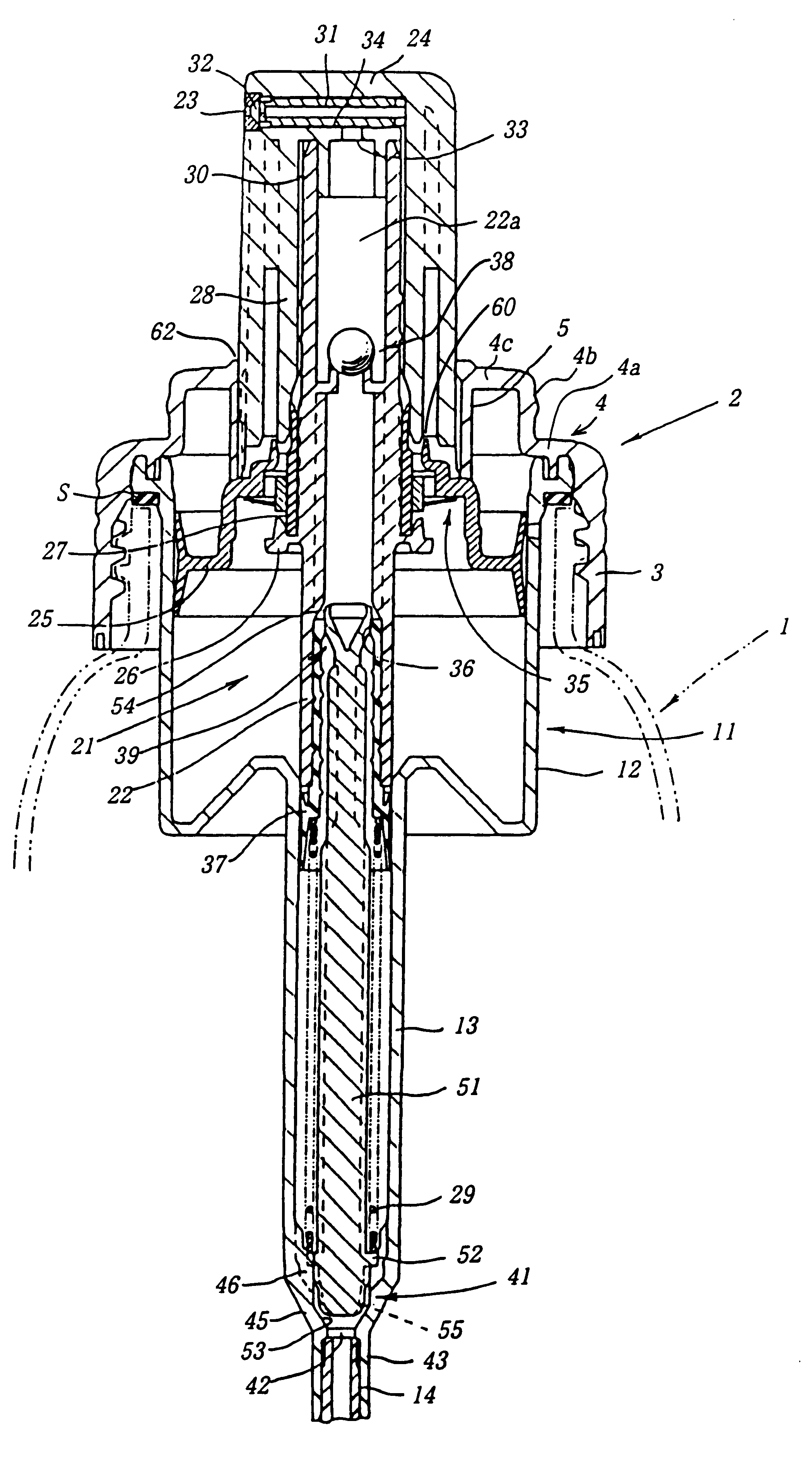
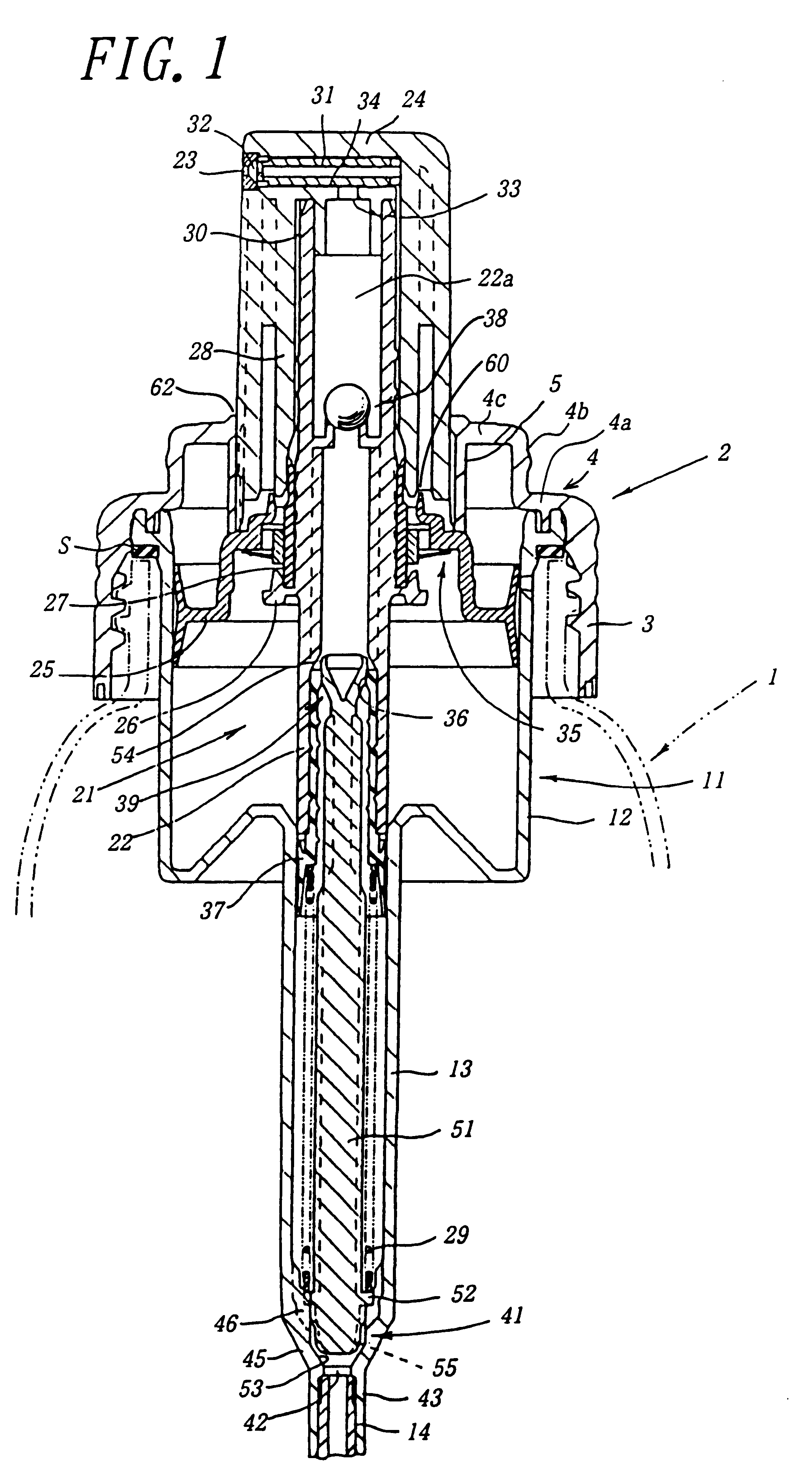
Further, when the operating member is pressed down, pressurized air inside the air cylinder immediately ejects through the air ejecting path. Therefore, it does not take a time until the liquid is atomized and ejected after the start of the ejection of air, different from the above-mentioned liquid suck-out / ejecting mechanism. Furthermore, when the press-down head moves to the upper, non-pressed down position, the valve body leaves the valve seat to form the large flow path, and the liquid is supplemented to the liquid flow path inside the stem through the always non-closed small flow path and the large flow path. In this way, the above-mentioned delay in ejecting the liquid can be overcome. Therefore, the phenomenon that the liquid and air cannot be mixed or atomized due to an excess amount of the liquid supplied at the time of the air ejection, as occurs in a spray device in which the liquid is sprayed under a high speed rotation, can be avoided.

Problems solved by technology

However, according to the conventional spray unit, as the air is ejected at a high speed, a negative pressure is generated due to the high speed of the air.
Therefore, this method is useful in that even a liquid having a relatively high viscosity is easily atomized, but there is a problem in that the mixture of air and liquid does not begin to spray until after air is continuously ejected for a while by pressing down the operating member, so that the start of the ejection of the liquid is delayed.

Method used


Image

  • Spray unit that atomizes liquid at the start of the spray operation
  • Spray unit that atomizes liquid at the start of the spray operation
  • Spray unit that atomizes liquid at the start of the spray operation

Examples


Embodiment Construction

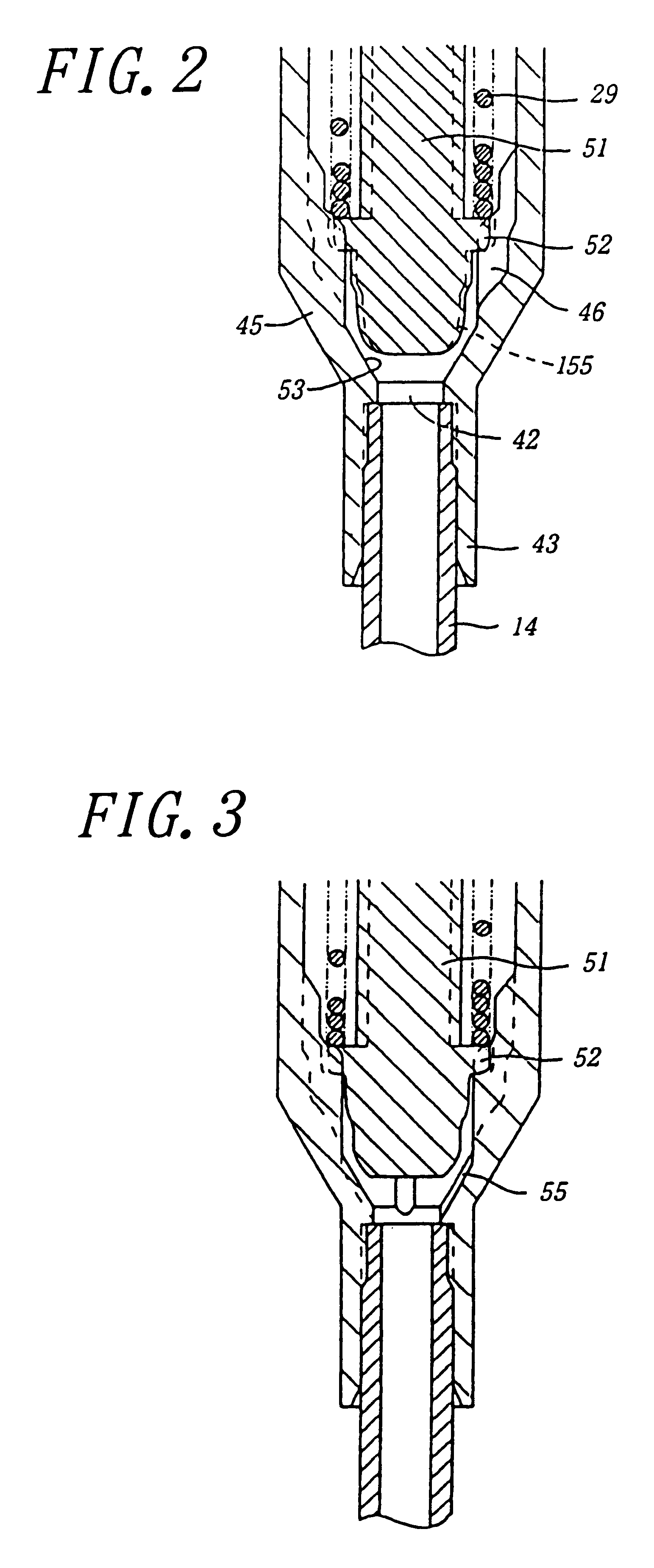
FIG. 1 is a sectional view of a principal portion of a spray device formed by attaching a spray unit according to the invention to an opening at a neck portion of a container 1. The spray unit is attached to the opening at the neck portion of the container 1 by means of a cap-shaped member 2. The cap-shaped member 2 includes a peripheral wall portion 3 screwed to an outer peripheral face of the neck portion of the container 1, a flanged top wall portion 4, and a stop cylindrical portion 5. The flanged top wall portion 4 including an annular portion 4a extending radially inward from an upper end of the peripheral wall portion 3, a cylindrical portion 4b extending axially outward from an inner peripheral portion of the annular portion 4a, and an annular portion 4c extending radially inward from an upper end of the cylindrical portion. The stop cylindrical portion 5 extends axially inward from an inner end portion of the annular portion 4c. The stop cylindrical portion 5 contacts an up...


PUM


Abstract

A spray unit that is attached to an opening at a neck portion of a container for spraying a liquid material in the container, including: a cylinder unit composed of a large-diameter air cylinder and a small-diameter liquid cylinder having a valve hole and an operating member. The operating member is composed of a large-diameter cylindrical piston, a stem having a check valve, and a press-down head having a spray nozzle hole. The liquid is to be sprayed when the operating member is pressed down. When the operating member is pressed down, a liquid flow-out path and an air ejecting path come together via a small gap inside the spray nozzle hole. The spray unit further includes a flow rate control valve is composed of a valve seat provided at an upper face of a valve hole of the liquid cylinder and a valve body arranged above the valve seat to be seated on or released from the valve seat. At least one of the valve seat and the valve body is provided with a small flow path that is not closed even when the valve body sits on the valve seat and that always communicates the interior of the container with the interior of the liquid cylinder, and the flow rate control valve is provided with a large flow path that is opened when the valve body is released from the valve seat and closed when the valve body sits on the valve seat. The sectional area of the small flow path is smaller than an open area of the valve hole of the air cylinder and that of the valve hole of the check valve provided inside the stem. The combination overcomes the delay in ejecting the liquid.

Description

1. Field of the InventionThe invention relates to apparatus for spraying liquid using a manually operated spray pump.2. Description of the Related ArtJP-A8-230,961 discloses a suction type spray device which is used in the state that the device is fitted to an opening of a neck portion of a container and which has a structure for spraying a liquid material inside the container.Such a suction type spray device has a cylinder unit including an upper large-diameter air cylinder hung into the container and a small-diameter liquid cylinder continued to a lower side of the air cylinder and an operating member including a large-diameter cylindrical piston gas-tightly and slidably held at an inner peripheral face of the large-diameter air cylinder. The spray device also has a stem that is gas-tightly engaged in the small-diameter liquid cylinder, upwardly urged and extended upwardly from the liquid cylinder, gas-tightly passing a central hole of the air cylinder, and provided with a check v...

Claims


Application Information

Patent Timeline
IPC IPC(8): B05B7/00B05B11/00B65D83/44
CPCB05B11/3087B05B7/0025B05B11/0064B05B11/0075B05B11/1087B05B11/00
Inventor MIZUSHIMA, HIROSHIKUWAHARA, KATSUHITOCHIKU, MASAMIIWATA, RISA
Owner YOSHINO KOGYOSHO CO LTD
Learn More